Nissan Primera P11. Manual - part 426


  Index      Nissan     Nissan Primera P11 (2001 year) - Service and Repair Manual


Search            


Content   ..  424  425  426  427   ..


Nissan Primera P11. Manual - part 426


WARNING:

I

Situate vehicle on a flat and solid surface.

I

Place chocks at front and back of rear wheels.

I

Do not remove engine until exhaust system has com-
pletely cooled down.

I

For safety during subsequent steps, the tension of wires
should be slackened against the engine.

I

Before removing front axle from transaxle, place safety
stands under designated front supporting points. Refer to
GI section for lifting points and towing.

I

Be sure to hoist engine and transaxle in a safe manner.

I

For engines not equipped with engine slingers, attach
proper slingers and bolts described in PARTS CATALOG
or Eurofast.

CAUTION:

I

When lifting engine, be careful not to strike adjacent parts,
especially accelerator wire casing, brake lines, and brake
master cylinder.

I

Always use engine slingers when hoisting the engine.

I

When removing drive shaft, be careful not to damage tran-
saxle oil seal.

1.

Remove engine undercovers and splash covers.

2.

Remove front exhaust tube.

3.

Disconnect lower water hose from radiator and drain coolant.

4.

Drain transaxle oil.
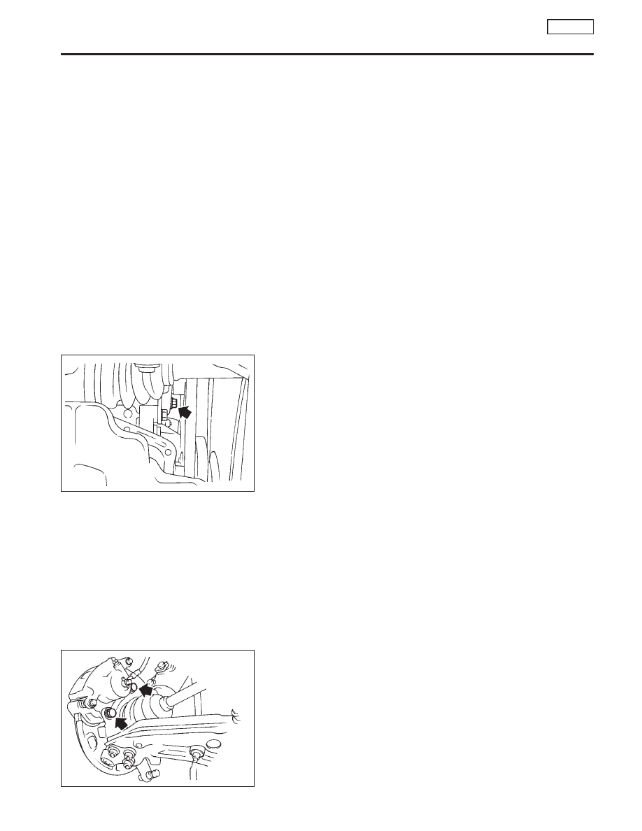
5.

Remove power steering mounting bolt. (See left.)

6.

Drain coolant from cylinder head.

7.

Disconnect water hoses and electrical wiring from radiator and
remove radiator.

8.

Disconnect fuel tubes and vacuum tubes.

9.

Release power steering belt adjusting nut and remove power
steering pump from engine.
Bind pump properly to the vehicle.

10. Remove A/C compressor.
11. Disconnect or remove electrical wiring where necessary.
12. Release clutch lever cable.
13. Release tachometer cable from transaxle housing.
14. Remove front wheels.

15. Remove brake caliper mounting bolts and bind caliper properly

to vehicle LH & RH.

.

SEM531D

SEM532D

ENGINE REMOVAL

CD20T

EM-163

16. Disconnect tie rod ball joints and lower ball joints (LH & RH).
17. Remove stabilizer.
18. Remove drive shafts from transaxle.
1)

RH: Split drive shaft center thrust bearing.

2)

RH & LH: Remove hub mounting bolts and remove drive shaft
carefully from transaxle.

19. Mount suitable slingers to cylinder head. Use a suitable hoist

to release the force on the engine mountings.

20. Remove upper mounting (Right side).

21. Release transaxle shift linkages.

22. Release left engine mounting.

SEM534D

SEM535D

SEM536D

ENGINE REMOVAL

CD20T

EM-164

23. Remove center member fixing bolts from chassis.

24. Remove engine with transaxle as shown.

SEM538D

.

SEM247D

ENGINE REMOVAL

CD20T

EM-165

Components

p

1

Piston ring

p

2

Piston

p

3

Piston pin

p

4

Connecting rod bearing

p

5

Connecting rod

p

6

Main bearing cap

p

7

Rear plate

p

8

Flywheel

p

9

Rear oil seal

p

10

Rear oil seal retainer

p

11

Gusset

p

12

Cylinder block

p

13

Main bearing

p

14

Crankshaft

p

15

Main bearing

p

16

Gusset

p

17

Drain plug

p

18

Pilot bushing

p

19

Plate

p

20

Oil jet

NEM376

54 - 74
(5.5 - 7.5,
40 - 54)

83 - 93
(8.5 - 9.5,
61 - 69)

69 - 78 (7.0 - 8.0, 51 - 58)

8.4 - 11.0 (0.86 - 1.12, 74.35 - 97.36)

30 - 40 (3.1 - 4.1, 22 - 30)

Refer to
“Assembly”

: Do not re-use.

: N·m (kg-m, in-lb)

üü

: N·m (kg-m, ft-lb)

ü

: Lubricate with new engine oil.

SEC. 110

120

30 - 40 (3.1 - 4.1, 22 - 30)

30 - 40 (3.1 - 4.1, 266 - 354)

30 - 40
(3.1 - 4.1, 22 - 30)

16 - 21 (1.6 - 2.1, 12 - 15)

16 - 21 (1.6 - 2.1, 12 - 15)

CYLINDER BLOCK

CD20T

Components

EM-166


Content   ..  424  425  426  427   ..