Nissan Primera P11. Manual - part 322


  Index      Nissan     Nissan Primera P11 (2001 year) - Service and Repair Manual


Search            


Content   ..  320  321  322  323   ..


Nissan Primera P11. Manual - part 322


Trouble Diagnoses (Models before VIN -
P11U0548750)

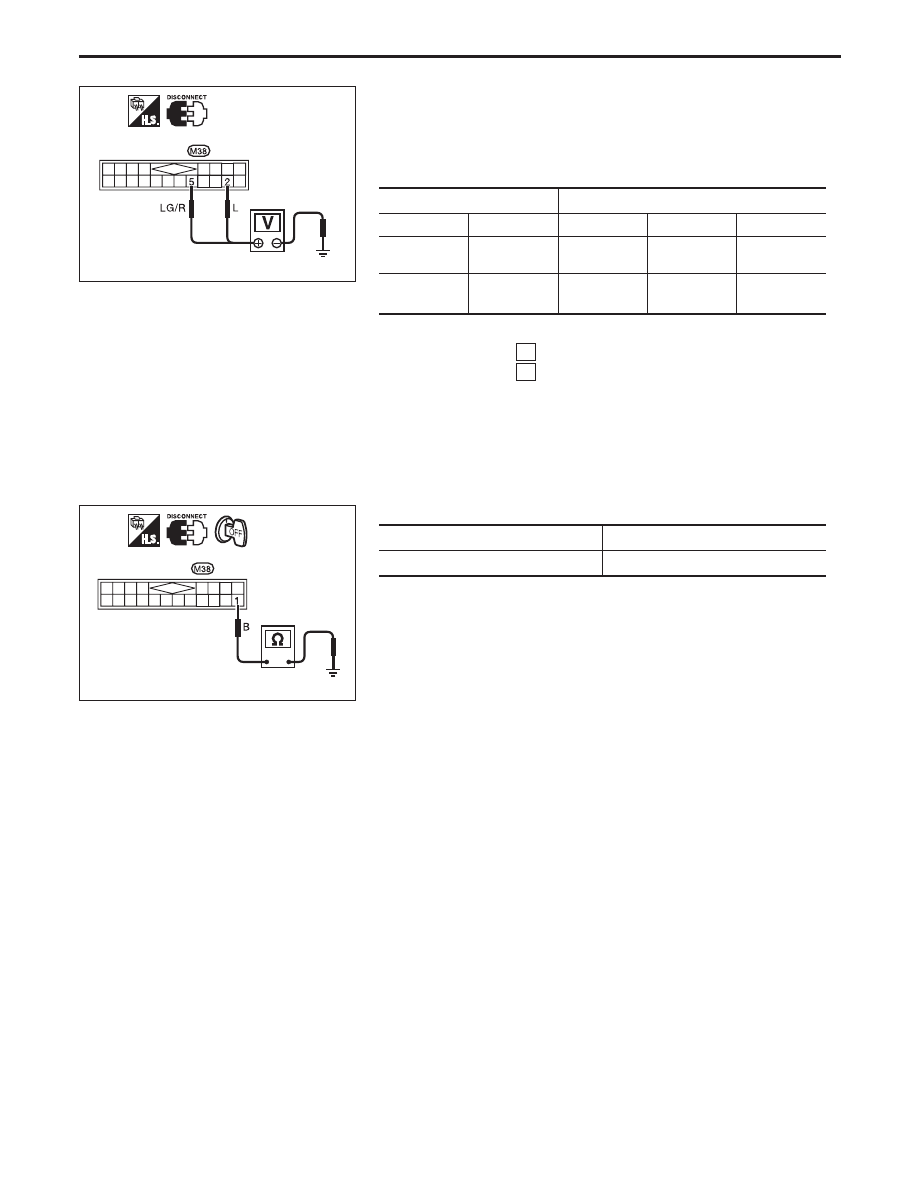
POWER SUPPLY AND GROUND CIRCUIT CHECK

Power supply circuit check

Terminals

Ignition switch position

OFF

ACC

ON

2

Ground

Battery
voltage

Battery
voltage

Battery
voltage

5

Ground

0V

0V

Battery
voltage

If NG, check the following,

10A fuse [No. 16 , located in fuse block (J/B)]

10A fuse [No. 12 , located in fuse block (J/B)]

Harness for open or short between fuse and combination
meter

Ground circuit check

Terminals

Continuity

1

- Ground

Yes

YEL489B

Combination meter
connector

YEL490B

Combination meter
connector

METER AND GAUGES

EL-155

INSPECTION/VEHICLE SPEED SENSOR

CHECK VEHICLE SPEED SENSOR OUT-
PUT.
1) Remove vehicle speed sensor from

transmission.

2) Check voltage between combination

meter terminals

3

and

1

while

quickly turning speed sensor pinion.

OK

NG

Vehicle speed sensor is OK.

CHECK POWER SOURCE.

Re-install vehicle speed sensor.

Turn ignition switch to “ON” position.

Check voltage between vehicle speed sen-
sor connector terminal

3

and ground.

Battery voltage should exist.

OK

NG

Check harness for open or
short between speedometer
and vehicle speed sensor.

CHECK GROUND CIRCUIT OF VEHICLE
SPEED SENSOR

Turn ignition switch to the “LOCK” posi-
tion.

Disconnect vehicle speed sensor connector.
Check continuity between vehicle speed
sensor harness connector terminal

1

and

body ground.

Continuity should exist.

OK

NG

Repair harness or connec-
tor

Check continuity between speedometer har-
ness connector terminal

3

and vehicle

speed sensor connector terminal

2

.

Continuity should exist.

OK

NG

Repair harness and connec-
tor.

Replace vehicle speed sensor.

YEL491B

Combination meter
connector

Vehicle speed
sensor

This connector should
remain connected.

Vehicle speed
sensor pinion

YEL493B

Combination meter connector

YEL494B

Vehicle speed sensor connectors

YEL495B

Vehicle speed
sensor
connectors

Combination
meter connector

METER AND GAUGES

Trouble Diagnoses (Models before VIN -
P11U0548750) (Cont’d)

EL-156

INSPECTION/ENGINE REVOLUTION SIGNAL

CHECK ECM OUTPUT.
1. Start engine.
2. Check voltage between combination

meter terminals

1

and

11

at idle and

2,000 rpm.

Higher rpm = Higher voltage
Lower rpm = Lower voltage
Voltage should change with rpm.

NG

OK

Engine revolution signal is
OK.

Check the following

Combination meter terminal

1

ground

circuit

Harness for open or short between ECM
and combination meter

INSPECTION/FUEL LEVEL SENSOR

CHECK GROUND CIRCUIT FOR
FUEL LEVEL SENSOR UNIT.
Check harness continuity between fuel
level sensor unit terminal

3

and

ground.

Continuity should exist.

OK

NG

Repair harness or con-
nector.

CHECK GAUGE UNITS.
Refer to “FUEL LEVEL SENSOR UNIT
CHECK” (EL-164).

OK

NG

Repair or replace.
Refer to FE section in
Service Manual.

CHECK HARNESS FOR OPEN OR
SHORT
1. Disconnect combination connector

and fuel level sensor unit connector.

2. Check continuity between combina-

tion meter terminal

20

and fuel

level sensor unit terminal

1

.

Continuity should exist.

3. Check continuity between combina-

tion meter

20

and ground.

Continuity should exist.

OK

NG

Repair harness or con-
nector.

Fuel level sensor is OK.

YEL492B

Combination meter connector

NEL764

Fuel level sensor
unit connector

NEL763

Combination meter
connector

Fuel level sensor unit
connector

METER AND GAUGES

Trouble Diagnoses (Models before VIN -
P11U0548750) (Cont’d)

EL-157

INSPECTION/THERMAL TRANSMITTER

CHECK THERMAL TRANSMITTER.
Refer to “THERMAL TRANSMITTER
CHECK ” (EL-164).

OK

NG

Repair or replace.

CHECK HARNESS FOR OPEN OR SHORT
1. Disconnect combination connector and

thermal transmitter connector.

2. Check continuity between combination

meter terminal

10

and thermal transmit-

ter terminal

1

.

Continuity should exist.

3. Check continuity between combination

meter terminal

10

and ground.

Continuity should exist.

OK

NG

Repair harness or connec-
tor.

Thermal transmitter is OK.

YEL498B

Combination meter
connector

Thermal transmitter
connector

METER AND GAUGES

Trouble Diagnoses (Models before VIN -
P11U0548750) (Cont’d)

EL-158


Content   ..  320  321  322  323   ..