Index Nissan Nissan Primera P11 (2001 year) - Service and Repair Manual
Search
Content .. 319 320 321 322 ..
Nissan Primera P11. Manual - part 321
YEL873C
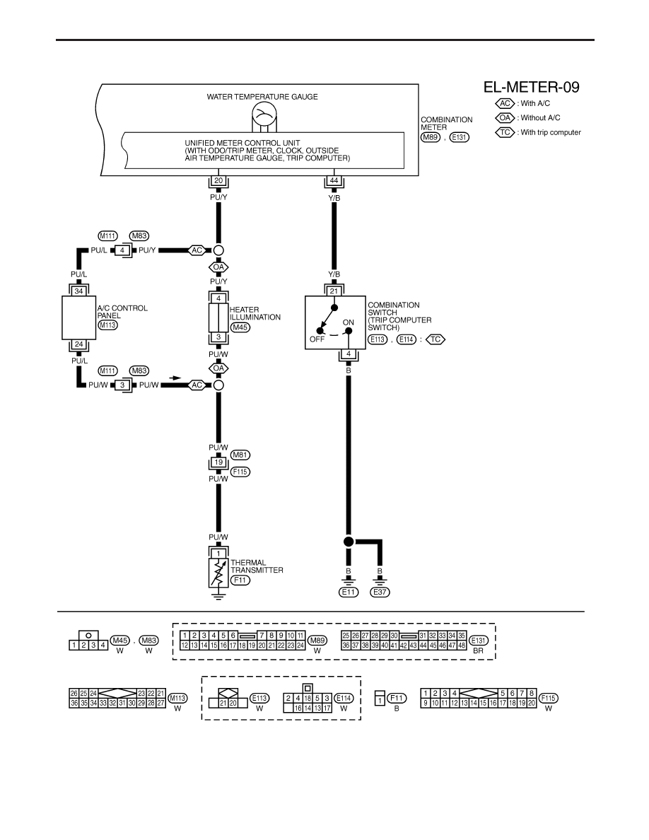
METER AND GAUGES
Wiring Diagram — METER —/CVT MODELSAFTER VIN - P11U0548750 (Cont’d)
EL-151