Nissan Primera P11. Manual - part 300
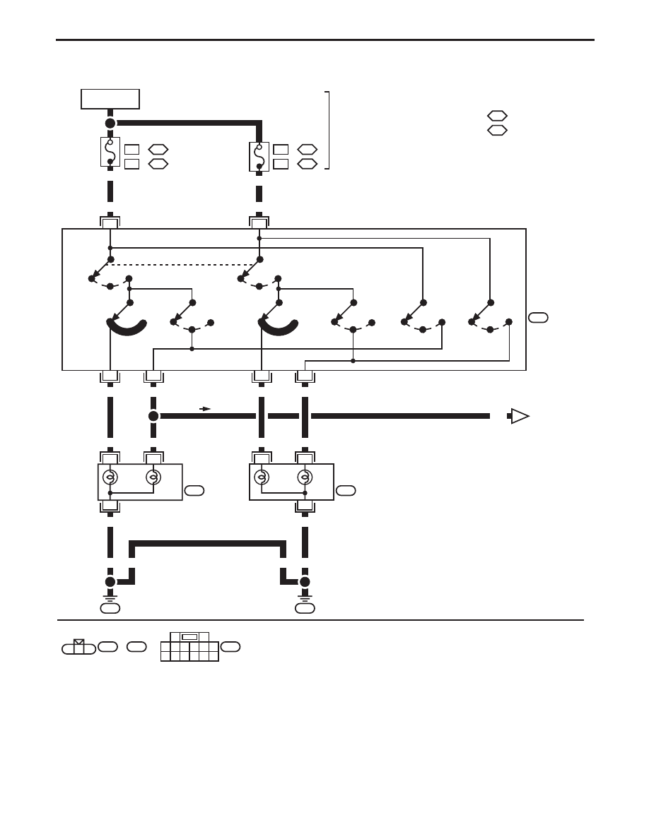
Wiring Diagram — H/LAMP —
YEL257B
9
10
2
5
8
R/W
R
R/B
R/Y
B
1
13
6
3
9
12
7
2
5
11
10
14
8
W
7
P/L
6
R/G
R/W
R
3
R/Y
1
R/B
E5
P/L
B
R/G
E32
E11
E37
GY
E5
,
GY
E32
3
2
1
:
:
:
:
R/B
A
EL-H/LAMP-01
E111
E111
B
B
GS
DI
15A
31
32
GS
DI
15A
32
33
GS
DI
B
B
3
2
1
BATTERY
Refer to EL-POWER.
: With gasoline engine
: With diesel engine
OFF
1ST
2ND
LOW
HIGH
PASS
OFF
1ST
2ND
LOW
HIGH
PASS
LOW
HIGH
PASS
LOW
HIGH
PASS
COMBINATION
SWITCH
(LIGHTING
SWITCH)
LOW
HIGH
HEADLAMP
LH
LOW
HIGH
HEADLAMP
RH
Next page
PASS
HIGH
LOW
PASS
HIGH
LOW
HEADLAMP (without Daytime Light System) — Conventional Type —
EL-67