Nissan Primera P11. Manual - part 298
쑗
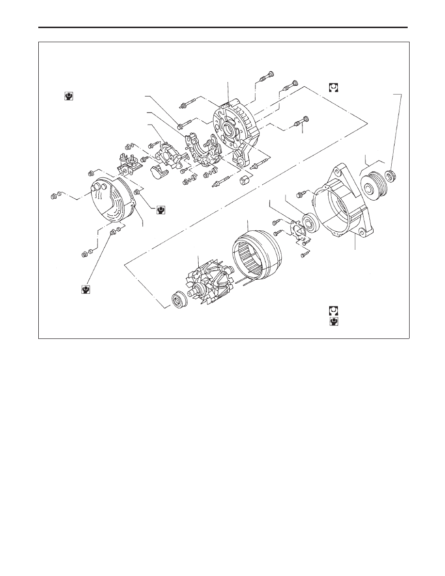
1
Pulley assembly
쑗
2
Front cover
쑗
3
Front bearing
쑗
4
Bearing retainer
쑗
5
Stator
쑗
6
Rotor
쑗
7
Special bolt
쑗
8
Rear cover
쑗
9
Diode assembly
쑗
10
Brush holder
쑗
11
Dust cover
YEL429B
쑗
8
쑗
7
쑗
1
쑗
2
쑗
3
쑗
4
쑗
5
쑗
6
3 - 4
(0.3 - 0.4, 27 - 35)
쑗
11
6 - 8
(0.6 - 0.8,
53 - 71)
쑗
10
쑗
9
3.5 - 5.5 (0.36 - 0.56, 31 - 49)
SEC. 231
A115I-80A
70 - 90
(7.1 - 9.2, 51.6 - 66.4)
: N·m (kg-m, ft-lb)
: N·m (kg-m, in-lb)
CHARGING SYSTEM
Construction (Cont’d)
EL-59