Nissan Primera P11. Manual - part 277
TERMI-
NAL
NO.
WIRE
COLOR
ITEM
CONDITION
DATA (DC Voltage)
36*1
G
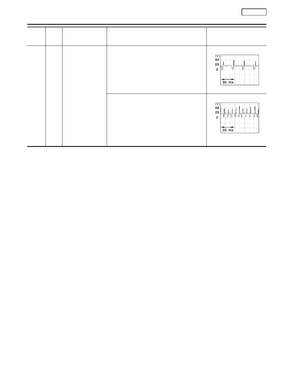
Ignition check
[Engine is running]
I
Warm-up condition
I
Idle speed
Approximately 13V
SEF998V
[Engine is running]
I
Engine speed is 2,000 rpm
Approximately 12V
SEF999V
*1: If so equipped
IGNITION SIGNAL
SR20DE
ECM Terminals and Reference Value (Cont’d)
EC-307