Nissan Primera P11. Manual - part 268
Component Description
NCEC0287
A closed throttle position switch and wide open throttle position
switch are built into the throttle position sensor unit. The wide open
throttle position switch is used only for CVT control.
When the throttle valve is in the closed position, the closed throttle
position switch sends a voltage signal to the ECM. The ECM only
uses this signal to open or close the EVAP canister purge control
valve when the throttle position sensor is malfunctioning.
CONSULT-II Reference Value in Data Monitor
Mode
NFEC0257
Specification data are reference values.
MONITOR ITEM
CONDITION
SPECIFICATION
CLSD THL/P SE
I
Engine: Idle
Throttle valve: Idle position
ON
Throttle valve: Slightly open
OFF
ECM Terminals and Reference Value
NCEC0288
Specification data are reference values and are measured between each terminal and 48 (ECM ground).
TER-
MINAL
NO.
WIRE
COLOR
ITEM
CONDITION
DATA (DC Voltage)
40
Y
Throttle position switch
(Closed position)
[Engine is running]
I
Accelerator pedal released
BATTERY VOLTAGE
(11 - 14V)
[Ignition switch “ON”]
I
Accelerator pedal depressed
Approximately 0V
On Board Diagnosis Logic
NCEC0289
DTC No.
Malfunction is detected when ...
Check Items (Possible Cause)
P0510
0510
I
Battery voltage from the closed throttle position switch is
sent to ECM with the throttle valve opened.
I
Harness or connectors
(The closed throttle position switch circuit is
shorted.)
I
Closed throttle position switch
I
Throttle position sensor
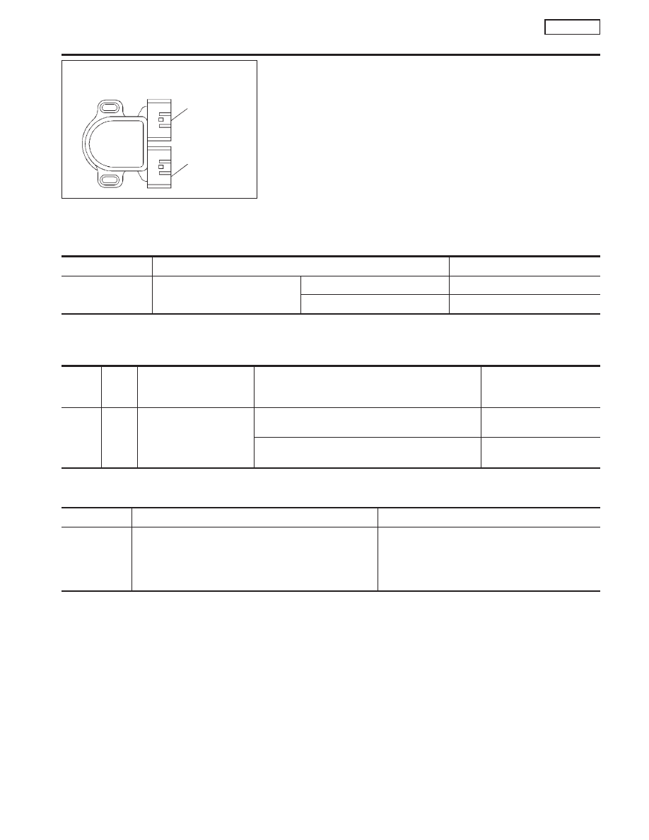
SEF505V
Throttle position switch
built into throttle
position sensor
Throttle position
switch connector
Throttle position
sensor connector
DTC P0510 CLOSED THROTTLE POSITION SWITCH
(IF SO EQUIPPED)
SR20DE
Component Description
EC-271