Nissan Primera P11. Manual - part 217
EXPLANATION FOR DRIVING PATTERNS EXCEPT FOR “MISFIRE <EXHAUST QUALITY
DETERIORATION>”, “FUEL INJECTION SYSTEM”
NCEC0033S06
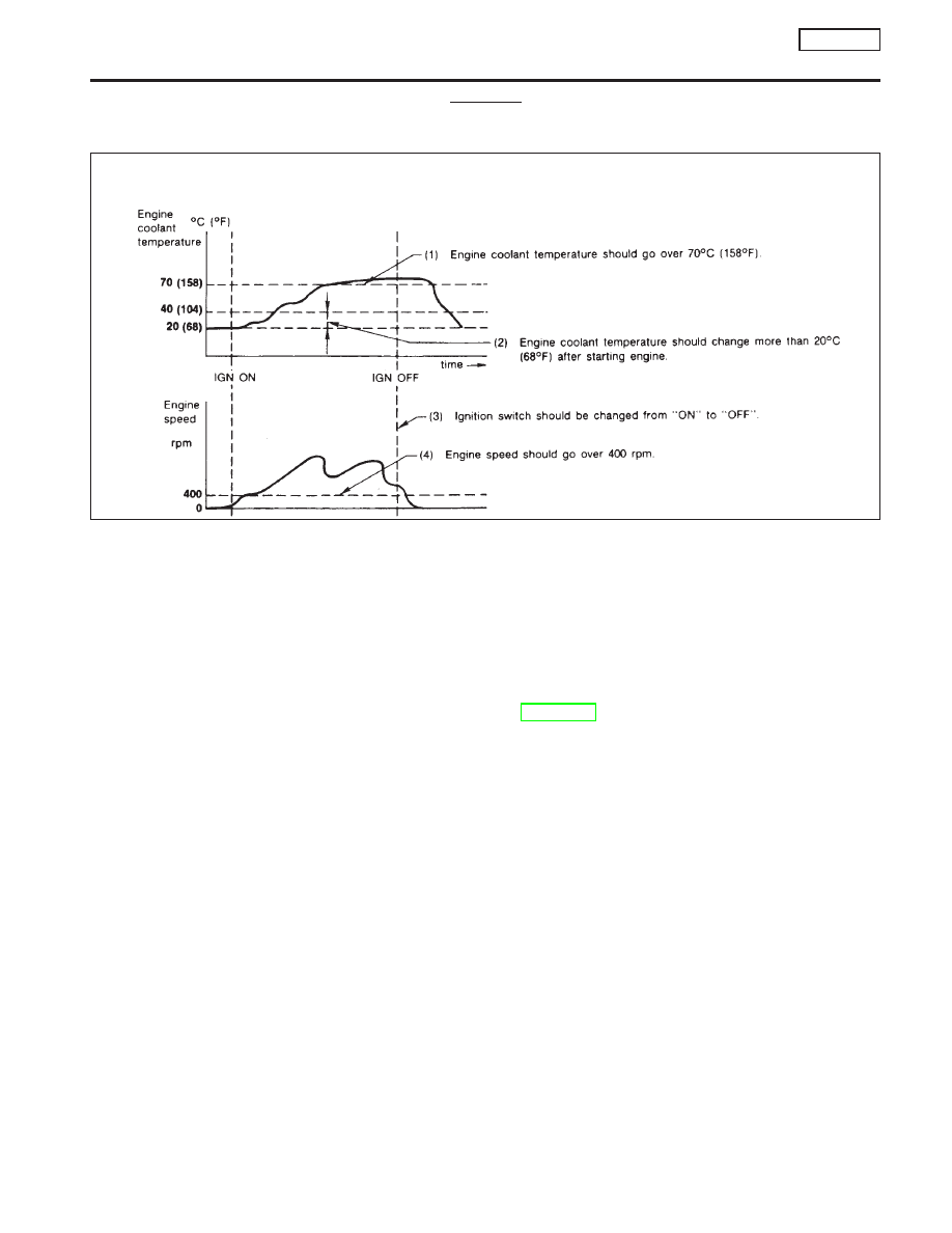
Driving Pattern A
NCEC0033S0601
I
The A counter will be cleared when the malfunction is detected regardless of (1) - (4).
I
The A counter will be counted up when (1) - (4) are satisfied without the same malfunction.
I
The DTC will not be displayed after the A counter reaches 40.
Driving Pattern B
NCEC0033S0602
Driving pattern B means the vehicle operation as follows:
All components and systems should be monitored at least once by the OBD system.
I
The B counter will be cleared when the malfunction is detected once regardless of the driving pattern.
I
The B counter will be counted up when driving pattern B is satisfied without any malfunctions.
I
The MI will go off when the B counter reaches 3 (*2 in EC-SR-66).
AEC574
ON BOARD DIAGNOSTIC SYSTEM DESCRIPTION
SR20DE
OBD System Operation Chart (Cont’d)
EC-67