Nissan Primera P11. Manual - part 205
Circuit Diagram
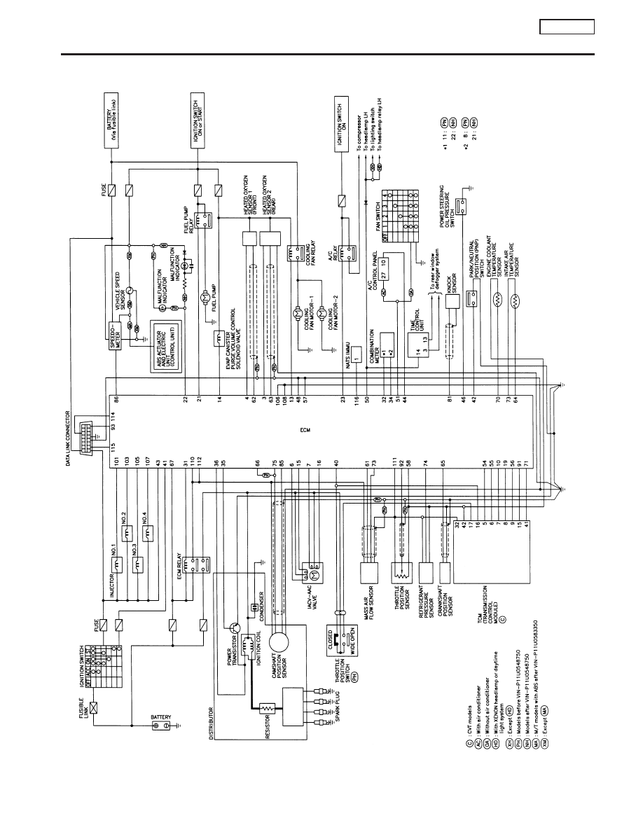
NCEC0010
YEC080A
ENGINE AND EMISSION CONTROL OVERALL SYSTEM
SR20DE
Circuit Diagram
EC-19
|
|
|
Circuit Diagram NCEC0010 YEC080A ENGINE AND EMISSION CONTROL OVERALL SYSTEM SR20DE Circuit Diagram EC-19 |