Nissan Primera P11. Manual - part 192
YEC794
Preceding
page
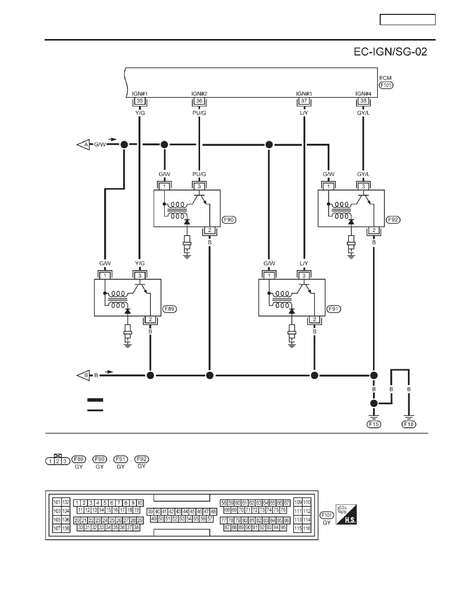
IGNITION
COIL No. 4
(WITH POWER
TRANSISTOR)
IGNITION
COIL No. 2
(WITH POWER
TRANSISTOR)
SPARK
PLUG
IGNITION
COIL No. 1
(WITH POWER
TRANSISTOR)
IGNITION
COIL No. 3
(WITH POWER
TRANSISTOR)
SPARK
PLUG
SPARK
PLUG
SPARK
PLUG
Preceding
page
: Detectable line for DTC
: Non-detectable line for DTC
IGNITION SIGNAL
QG16
I
18DE
Wiring Diagram (Cont’d)
EC-325