Nissan Primera P11. Manual - part 193
10
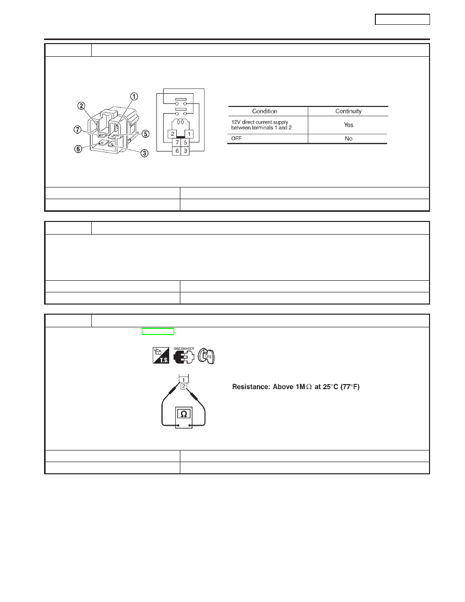
CHECK ECM RELAY
1. Apply 12V direct current between ECM relay terminals 1 and 2.
2. Check continuity between ECM relay terminals 3 and 5, 6 and 7.
SEF296X
OK or NG
OK
©
GO TO 18.
NG
©
Replace ECM relay.
11
CHECK CONDENSER GROUND CIRCUIT FOR OPEN AND SHORT
1. Turn ignition switch OFF.
2. Check harness continuity between condenser terminal 2 and engine ground. Refer to wiring diagram.
Continuity should exist.
3. Also check harness for short to ground and short to power.
OK or NG
OK
©
GO TO 12.
NG
©
Repair open circuit or short to ground or short to power in harness or connectors.
12
CHECK CONDENSER
Refer to “Component Inspection”, EC-QG-331.
SEF369X
OK or NG
OK
©
GO TO 13.
NG
©
Replace condenser.
IGNITION SIGNAL
QG16
I
18DE
Diagnostic Procedure (Cont’d)
EC-329