Nissan Primera P11. Manual - part 175
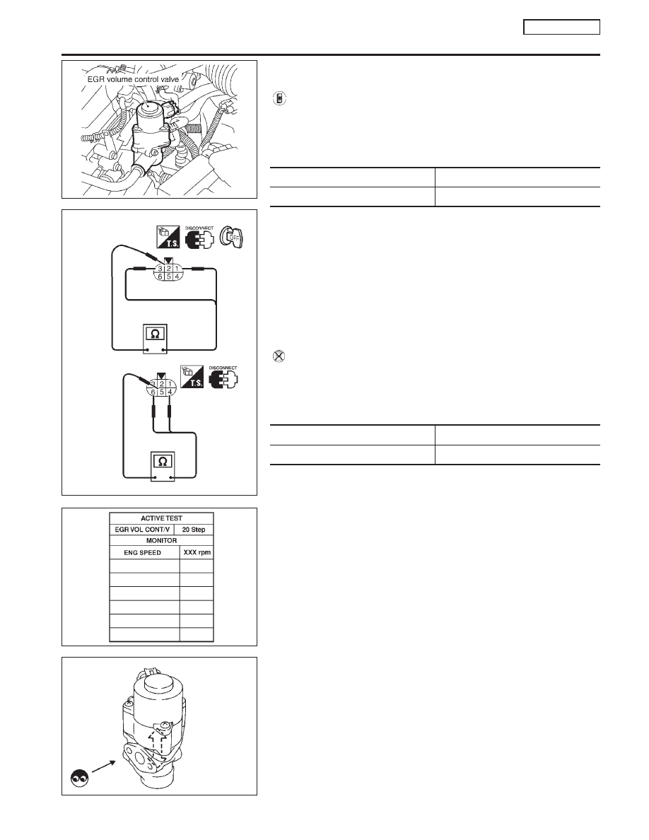
Component Inspection
NCEC0512
EGR VOLUME CONTROL VALVE
NCEC0512S01
With CONSULT-II
1)
Disconnect EGR volume control valve harness connector.
2)
Check resistance between the following terminals.
terminal 2 and terminals 1, 3
terminal 5 and terminals 4, 6
Temperature °C (°F)
Resistance
Ω
20 (68)
20 - 24
3)
Reconnect EGR volume control valve harness connector.
4)
Remove EGR volume control valve from cylinder head.
(The EGR volume control valve harness connector should
remain connected.)
5)
Turn ignition switch “ON”.
6)
Perform “EGR VOL CONT/V” in “ACTIVE TEST” mode with
CONSULT-II. Check that EGR volume control valve shaft
moves smoothly forward and backward according to the valve
opening.
If NG, replace the EGR volume control valve.
Without CONSULT-II
1)
Disconnect EGR volume control valve harness connector.
2)
Check resistance between the following terminals.
terminal 2 and terminals 1, 3
terminal 5 and terminals 4, 6
Temperature °C (°F)
Resistance
Ω
20 (68)
20 - 24
3)
Turn ignition switch “ON” and “OFF”. Check that EGR volume
control valve shaft moves smoothly forward and backward
according to the ignition switch position.
If NG, replace the EGR volume control valve.
SEF069X
SEF558W
NEF109A
SEF560W
DTC P0403 EGR VOLUME CONTROL VALVE (CIRCUIT)
(IF SO EQUIPPED)
QG16
I
18DE
Component Inspection
EC-257