Nissan Primera P11. Manual - part 167


  Index      Nissan     Nissan Primera P11 (2001 year) - Service and Repair Manual


Search            


Content   ..  165  166  167  168   ..


Nissan Primera P11. Manual - part 167


6

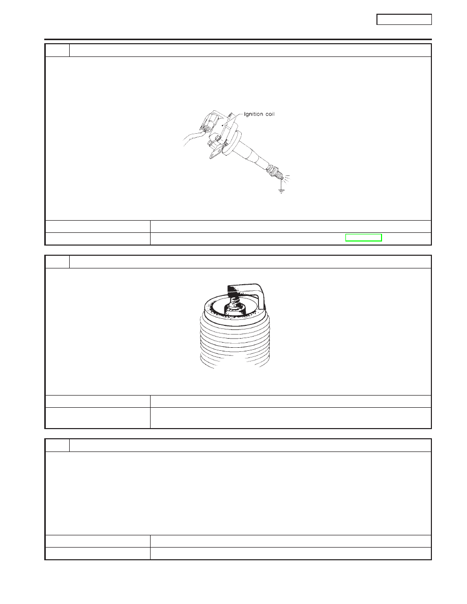
CHECK IGNITION SPARK

1. Turn Ignition switch “OFF”.
2. Disconnect ignition coil assembly from rocker cover.
3. Connect a known good spark plug to the ignition coil assembly.
4. Place end of spark plug against a suitable ground and crank engine.
5. Check for spark.

SEF575Q

OK or NG

OK

©

GO TO 7.

NG

©

Check ignition coil, power transistor and their circuits. Refer to EC-QG-323.

7

CHECK SPARK PLUGS

Remove the spark plugs and check for fouling, etc.

SEF156I

OK or NG

OK

©

GO TO 8.

NG

©

Repair or replace spark plug(s) with standard type one(s). For spark plug type, refer to
“ENGINE MAINTENANCE” in MA section.

8

CHECK COMPRESSION PRESSURE

Refer to EM section.

I

Check compression pressure.

Standard:

1,324 kPa (13.24 bar, 13.5 kg/cm

2

, 192 psi)/350 rpm

Minimum:

1,128 kPa (11.28 bar, 11.5 kg/cm

2

, 164 psi)/350 rpm

Difference between each cylinder:

98 kPa (0.98 bar, 1.0 kg/cm

2

, 14 psi)/350 rpm

OK or NG

OK

©

GO TO 9.

NG

©

Check pistons, piston rings, valves, valve seats and cylinder head gaskets.

DTC P0300 - P0304 NO. 4 - 1 CYLINDER MISFIRE,

MULTIPLE CYLINDER MISFIRE

QG16

I

18DE

Diagnostic Procedure (Cont’d)

EC-225

9

CHECK FUEL PRESSURE

1. Install any parts removed.
2. Release fuel pressure to zero. Refer to EC-QG-29.
3. Install fuel pressure gauge and check fuel pressure.

SEF925W

At idle: Approx. 235 kPa (2.35 bar, 2.4 kg/cm

2

, 34 psi)

OK or NG

OK

©

GO TO 11.

NG

©

GO TO 10.

10

DETECT MALFUNCTIONING PART

Check the following.

I

Fuel pump and circuit Refer to EC-QG-336.

I

Fuel pressure regulator Refer to EC-QG-30.

I

Fuel lines Refer to “ENGINE MAINTENANCE” in MA section.

I

Fuel filter for clogging

©

Repair or replace.

11

CHECK IGNITION TIMING

Perform “Basic Inspection”.
Refer to EC-QG-72.

OK or NG

OK

©

GO TO 12.

NG

©

1. Perform “Idle Air Volume Learning”. Refer to EC-QG-33.
2. Check camshaft position sensor (PHASE) (EC-QG-238) and crankshaft position sen-

sor (POS) (EC-QG-232).

12

CHECK HEATED OXYGEN SENSOR 1 (FRONT)

Refer to “Component Inspection”, EC-QG-231.

OK or NG

OK

©

GO TO 13.

NG

©

Replace Heated oxygen sensor 1 (front).

DTC P0300 - P0304 NO. 4 - 1 CYLINDER MISFIRE,

MULTIPLE CYLINDER MISFIRE

QG16

I

18DE

Diagnostic Procedure (Cont’d)

EC-226

13

CHECK MASS AIR FLOW SENSOR

With CONSULT-II

Check “MASS AIR FLOW” in “DATA MONITOR” mode with CONSULT-II.

at idling: 1.0 - 4.0 g

m/sec

at 2,500 rpm: 5.0 - 10.0 g

m/sec

With GST

Check mass air flow sensor signal in MODE 1 with GST.

at idling: 1.0 - 4.0 g

m/sec

at 2,500 rpm: 5.0 - 10.0 g

m/sec

OK or NG

OK

©

GO TO 15.

NG

©

GO TO 14.

14

CHECK CONNECTORS

Check connectors for rusted terminals or loose connections in the mass air flow sensor circuit or engine grounds.
Refer to EC-QG-110.

OK or NG

NG

©

Repair or replace it.

15

CHECK SYMPTOM MATRIX CHART

Check items on the rough idle symptom in “Symptom Matrix Chart”, EC-QG-82.

OK or NG

OK

©

GO TO 16.

NG

©

Repair or replace.

16

ERASE THE 1ST TRIP DTC

Some tests may cause a 1st trip DTC to be set.
Erase the 1st trip DTC from the ECM memory after performing the tests. Refer to EC-QG-44.

©

GO TO 17.

17

CHECK INTERMITTENT INCIDENT

Perform “TROUBLE DIAGNOSIS FOR INTERMITTENT INCIDENT”, EC-QG-102.

©

INSPECTION END

DTC P0300 - P0304 NO. 4 - 1 CYLINDER MISFIRE,

MULTIPLE CYLINDER MISFIRE

QG16

I

18DE

Diagnostic Procedure (Cont’d)

EC-227

Component Description

NCEC0206

The knock sensor is attached to the cylinder block. It senses
engine knocking using a piezoelectric element. A knocking vibration
from the cylinder block is sensed as vibrational pressure. This
pressure is converted into a voltage signal and sent to the ECM.
Freeze frame data will not be stored in the ECM for the knock
sensor. The MI will not light for knock sensor malfunction. The
knock sensor has one trip detection logic.

ECM Terminals and Reference Value

NCEC0207

Specification data are reference values and are measured between each terminal and ground.

CAUTION:

Do not use ECM ground terminals when measuring input/output voltage. Doing so may result in dam-
age to the ECM’s transistor. Use a ground other than ECM terminals, such as the ground.

TERMI-

NAL

NO.

WIRE

COLOR

ITEM

CONDITION

DATA (DC Voltage)

81

W

Knock sensor

[Engine is running]

I

Idle speed

1.0 - 4.0V

On Board Diagnosis Logic

NCEC0208

DTC No.

Malfunction is detected when ...

Check Items (Possible Cause)

P0325
0325

I

An excessively low or high voltage from the knock sen-
sor is sent to ECM.

I

Harness or connectors
(The knock sensor circuit is open or shorted.)

I

Knock sensor

DTC Confirmation Procedure

NCEC0209

NOTE:
If “DTC Confirmation Procedure” has been previously conducted,
always turn ignition switch “OFF” and wait at least 9 seconds
before conducting the next test.
TESTING CONDITION:
Before performing the following procedure, confirm that bat-
tery voltage is more than 10V at idle.

With CONSULT-II

1)

Turn ignition switch “ON” and select “DATA MONITOR” mode
with CONSULT-II.

2)

Start engine and run it for at least 5 seconds at idle speed.

3)

If DTC is detected, go to “Diagnostic Procedure”, EC-QG-230.

With GST

Follow the procedure “With CONSULT-II” above.

SEF598K

NEF068A

DTC P0325 KNOCK SENSOR (KS)

QG16

I

18DE

Component Description

EC-228


Content   ..  165  166  167  168   ..