Nissan Primera P11. Manual - part 165
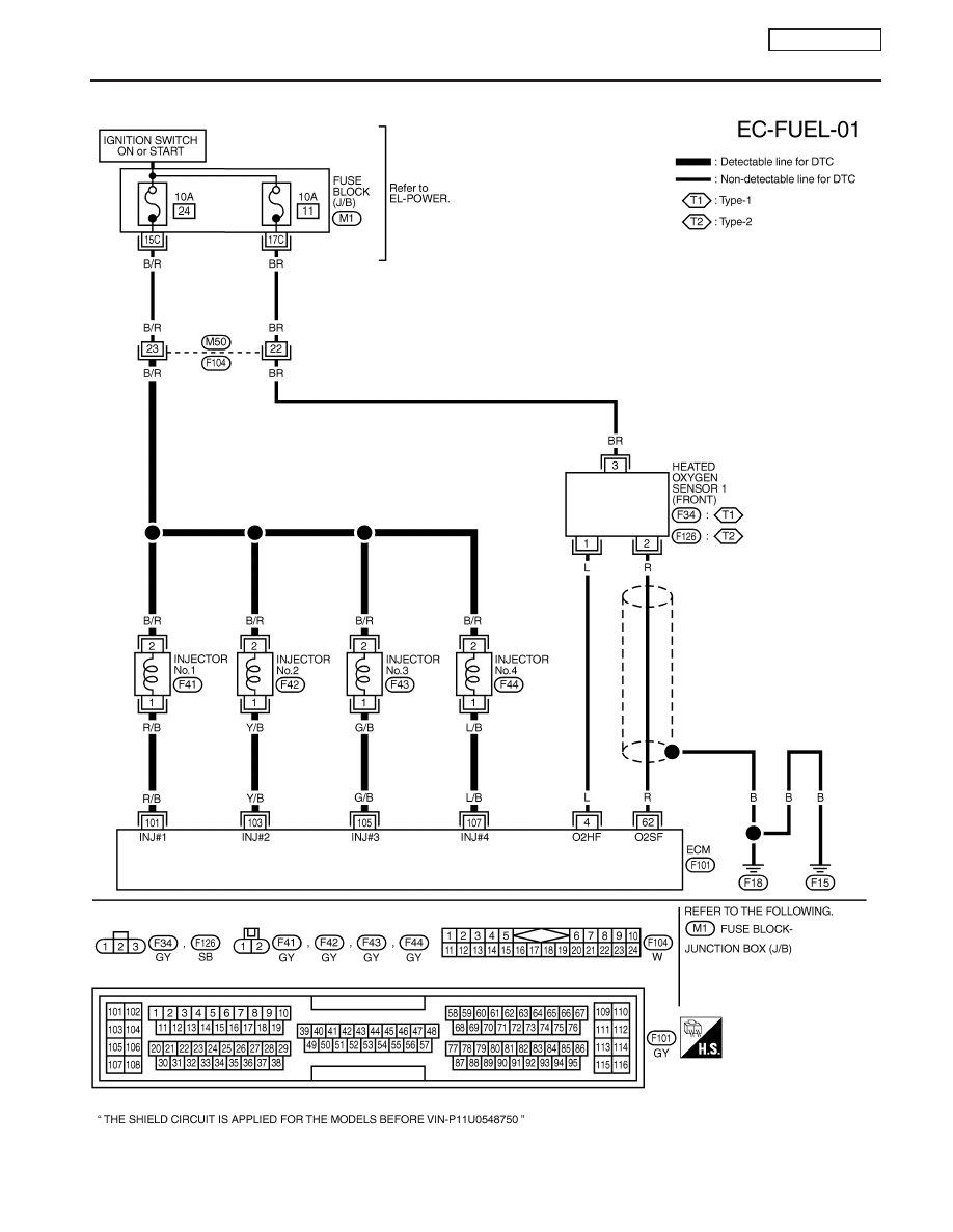
Wiring Diagram
NCEC0194
YEC069A
DTC P0172 FUEL INJECTION SYSTEM FUNCTION
(RICH SIDE)
QG16
I
18DE
Wiring Diagram
EC-217
|
|
|
Wiring Diagram NCEC0194 YEC069A DTC P0172 FUEL INJECTION SYSTEM FUNCTION (RICH SIDE) QG16 I 18DE Wiring Diagram EC-217 |