Nissan Primera P11. Manual - part 168
Wiring Diagram
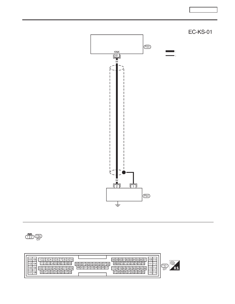
NCEC0210
YEC269
Detectable line for DTC
Non-detectable line for DTC
ECM
KNOCK
SENSOR
DTC P0325 KNOCK SENSOR (KS)
QG16
I
18DE
Wiring Diagram
EC-229
|
|
|
Wiring Diagram NCEC0210 YEC269 Detectable line for DTC Non-detectable line for DTC ECM KNOCK DTC P0325 KNOCK SENSOR (KS) QG16 I 18DE Wiring Diagram EC-229 |