Nissan Primera P11. Manual - part 139


  Index      Nissan     Nissan Primera P11 (2001 year) - Service and Repair Manual


Search            


Content   ..  137  138  139  140   ..


Nissan Primera P11. Manual - part 139


Diagnostic Procedure

NCEC0057

1

INSPECTION START

Which malfunction (A, or B) is duplicated?

Malfunction A or B

A

©

GO TO 3.

B

©

GO TO 2.

2

CHECK INTAKE SYSTEM

Check the following for connection.

I

Air duct

I

Vacuum hoses

I

Intake air passage between air duct to collector

OK or NG

OK

©

GO TO 3.

NG

©

Reconnect the parts.
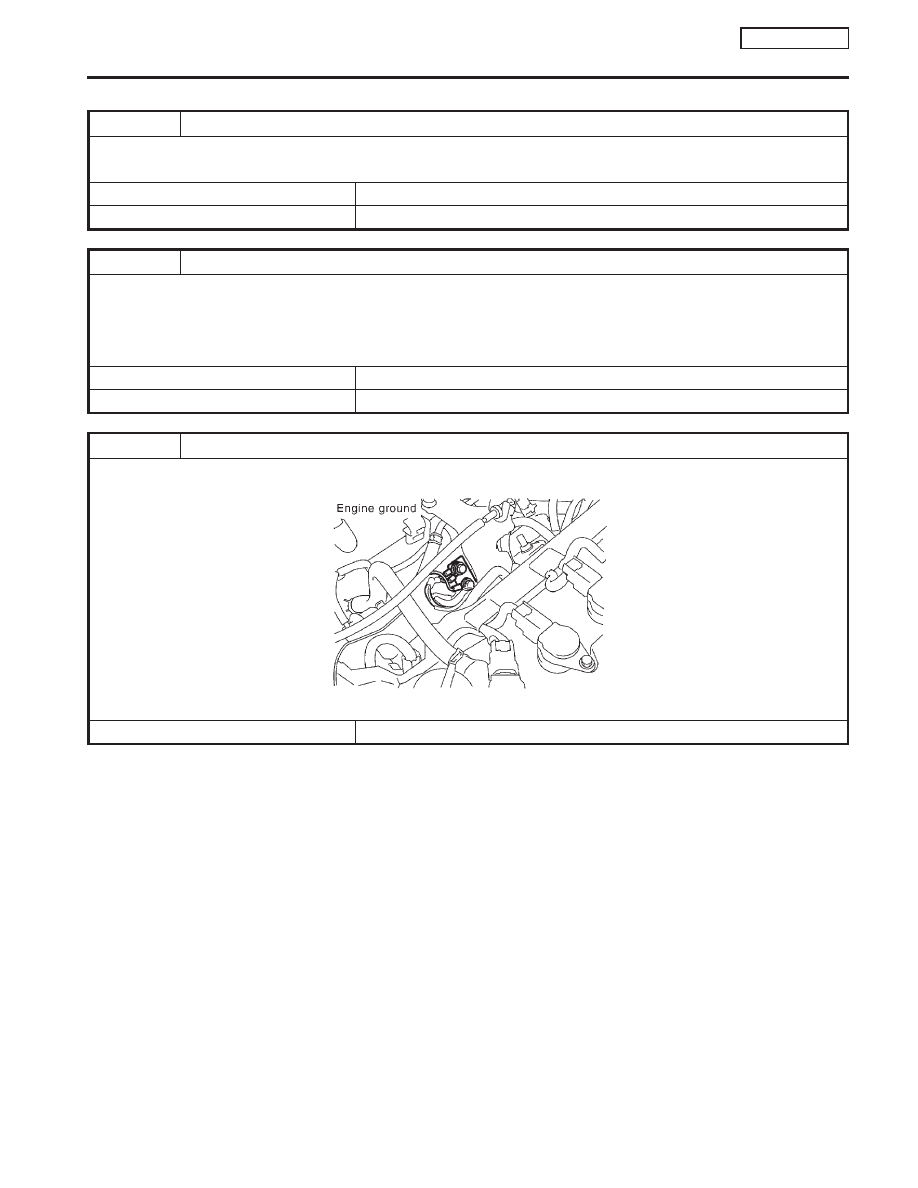
3

RETIGHTEN GROUND SCREWS

1. Turn ignition switch “OFF”.
2. Loosen and retighten engine ground screws.

SEF994W

©

GO TO 4.

DTC P0100 MASS AIR FLOW SENSOR (MAFS)

QG16

I

18DE

Diagnostic Procedure

EC-113

4

CHECK POWER SUPPLY

1. Disconnect mass air flow sensor harness connector.

SEF995W

2. Turn ignition switch “ON”.
3. Check voltage between terminals 2, 4 and ground with CONSULT-II or tester.

SEF996W

Voltage: Battery voltage

OK or NG

OK

©

GO TO 6.

NG

©

GO TO 5.

5

DETECT MALFUNCTIONING PART

Check the following.

I

Harness connectors E90, F73

I

Harness for open or short between ECM relay and mass air flow sensor

I

Harness for open or short between mass air flow sensor and ECM

©

Repair harness or connectors.

6

CHECK GROUND CIRCUIT

1. Turn ignition switch “OFF”.
2. Disconnect ECM harness connector.
3. Check harness continuity between mass air flow sensor harness connector terminal 3 and ECM terminal 73.

Refer to wiring diagram.

Continuity should exist.

4. Also check harness for short to ground and short to power.

OK or NG

OK

©

GO TO 7.

NG

©

Repair open circuit or short to ground or short to power in harness or connectors.

DTC P0100 MASS AIR FLOW SENSOR (MAFS)

QG16

I

18DE

Diagnostic Procedure (Cont’d)

EC-114

7

CHECK INPUT SIGNAL CIRCUIT

1. Check harness continuity between mass air flow sensor harness connector terminal 5 and ECM terminal 61.

Refer to wiring diagram.

Continuity should exist.

2. Also check harness for short to ground and short to power.

OK or NG

OK

©

GO TO 8.

NG

©

Repair open circuit or short to ground or short to power in harness or connectors.

8

CHECK MASS AIR FLOW SENSOR

Refer to “Component Inspection”, EC-QG-115.

OK or NG

OK

©

GO TO 9.

NG

©

Replace mass air flow sensor.

9

CHECK INTERMITTENT INCIDENT

Perform “TROUBLE DIAGNOSIS FOR INTERMITTENT INCIDENT”, EC-QG-102.

©

INSPECTION END

Component Inspection

NCEC0058

MASS AIR FLOW SENSOR

NCEC0058S01

1.

Turn ignition switch “ON”.

2.

Start engine and warm it up to normal operating temperature.

3.

Check voltage between ECM terminal 61 (Mass air flow sen-
sor signal) and ground.

Conditions

Voltage V

Ignition switch “ON” (Engine stopped.)

Less than 1.2

Idle (Engine is warmed-up to normal operating
temperature.)

1.0 - 1.7

2,500 rpm (Engine is warmed-up to normal operat-
ing temperature.)

1.7 - 2.1

Idle to about 4,000 rpm*

1.0 - 1.7 to Approx. 4.0

*: Check for linear voltage rise in response to increases to about 4,000 rpm in
engine speed.

4.

If the voltage is out of specification, disconnect mass air flow
sensor harness connector and connect it again. Repeat above
check.

5.

If NG, remove mass air flow sensor from air duct. Check hot
film for damage or dust.

SEF993W

SEF987W

DTC P0100 MASS AIR FLOW SENSOR (MAFS)

QG16

I

18DE

Diagnostic Procedure (Cont’d)

EC-115

Component Description

NCEC0066

The intake air temperature sensor is built into the mass air flow
sensor. The sensor detects intake air temperature and transmits a
signal to the ECM.
The temperature sensing unit uses a thermistor which is sensitive
to the change in temperature. Electrical resistance of the thermistor
decreases in response to the temperature rise.

<Reference data>

Intake air temperature

°C (°F)

Voltage*

V

Resistance

k

20 (68)

3.5

2.2 - 2.6

80 (176)

1.23

0.31 - 0.37

*: These data are reference values and are measured between ECM terminal 64
(Intake air temperature sensor) and ground.

CAUTION:

Do not use ECM ground terminals when measuring input/
output voltage. Doing so may result in damage to the ECM’s
transistor. Use a ground other than ECM terminals, such as
the ground.

On Board Diagnosis Logic

NCEC0067

DTC No.

Malfunction is detected when ...

Check Items (Possible Cause)

P0110
0110

An excessively low or high voltage from the sensor is sent
to ECM.

I

Harness or connectors
(The sensor circuit is open or shorted.)

I

Intake air temperature sensor

DTC Confirmation Procedure

NCEC0068

NOTE:
If “DTC Confirmation Procedure” has been previously conducted,
always turn ignition switch “OFF” and wait at least 9 seconds
before conducting the next test.

With CONSULT-II

1)

Turn ignition switch “ON”.

2)

Select “DATA MONITOR” mode with CONSULT-II.

3)

Wait at least 5 seconds.

4)

If 1st trip DTC is detected, go to “Diagnostic Procedure”, EC-
QG-118.

With GST

Follow the procedure “With CONSULT-II” above.

SEF987W

SEF012P

NEF068A

DTC P0110 INTAKE AIR TEMPERATURE SENSOR

QG16

I

18DE

Component Description

EC-116


Content   ..  137  138  139  140   ..