Nissan Primera P11. Manual - part 79
Description
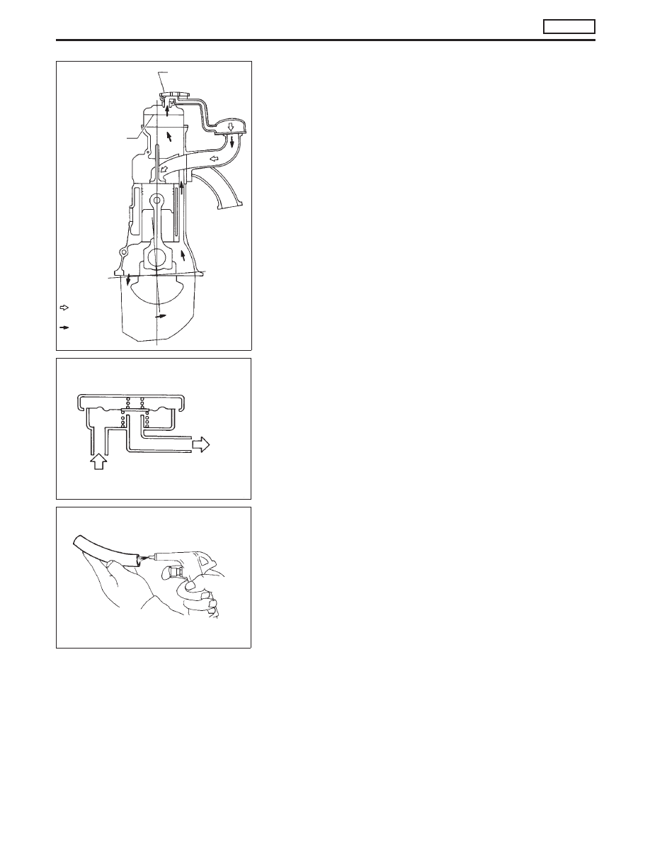
●
In this system blow-by gas is sucked into the air inlet pipe
through the control valve after oil separation by the oil sepa-
rator in the rocker cover.
Blow-by Control Valve
●
Check control valve for clogging and abnormalities.
Ventilation Hose
1. Check hoses and hose connections for leaks.
2. Disconnect all hoses and clean with compressed air.
If any hose cannot be freed of obstructions, replace.
SEF851S
Blow-by control
valve
FRESH AIR
BLOW BY
GAS
Baffle plate
SEC586B
Blow-by control valve
Rocker cover
Intake
manifold
SEC692
CRANKCASE VENTILATION SYSTEM
CD20T
EC-21