Nissan Primera P11. Manual - part 72


  Index      Nissan     Nissan Primera P11 (2001 year) - Service and Repair Manual


Search            


Content   ..  70  71  72  73   ..


Nissan Primera P11. Manual - part 72


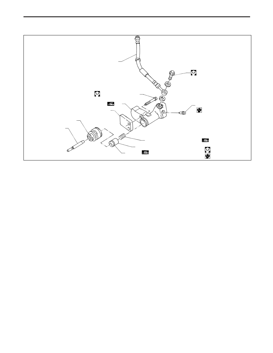
Clutch Operating Cylinder

INSPECTION

Check contact surfaces of cylinder for wear, rust or damage.
Replace if necessary.

Check piston and piston cup for wear or damage. Replace if
necessary

Check piston spring for wear or damage. Replace if neces-
sary.

Check dust cover for cracks, deformation or damage.
Replace if necessary.

NCL008

18 - 25 (1.9 - 2.5, 14 - 18)

Hydraulic pipe

Air bleeder valve

7 - 9 (0.8 - 0.9, 62 - 79)

30 - 38 (3.1 - 3.8, 23 - 28)

Operating cylinder

p

R

Spacer

Dust cover

Push rod

Spring

Piston assembly

Piston cup

p

R

p

R

: Apply rubber

grease

: N·m (kg-m, ft-lb)

: N·m (kg-m, in-lb)

SEC. 306

HYDRAULIC CLUTCH CONTROL

CL-9

Clutch Damper

DISASSEMBLY AND ASSEMBLY

1. Remove damper assembly mounting bolts.
2. Remove gasket, damper rubber, plate, piston assembly, and

piston spring from cylinder body.

3. Clean gasket contact surface on cylinder body and damper

bracket with scrapers.

CAUTION:

Be careful not to scratch the contact surface.

INSPECTION

Check cylinder and piston contact surfaces for uneven wear,
rust or damage. Replace if necessary.

Check damper rubber and piston cup for cracks, deformation
or damage. Replace if necessary.

NCL009

Bleeder Screw

6 - 10
(0.7 - 1.0,
54 - 88)

Cylinder body

Gasket

Damper cover
(LHD model)

2.9 - 5.9
(0.29 - 0.60,
26 - 52)

5.1 - 6.5
(0.52 - 0.66, 46 - 57)

Damper rubber

p

R

Contact surface to piston assembly

Plate

Piston assembly

Piston cup

p

R

p

R

Rubbing sur-

face to piston assembly

Spring

: Do not re-use

: N·m (kg-m, in-lb)

p

R

: Apply rubber grease

SEC. 306

HYDRAULIC CLUTCH CONTROL

CL-10

REMOVAL AND INSTALLATION

1. Remove manual transaxle from vehicle. Refer to MT section

“REMOVAL AND INSTALLATION”.

2. Remove release bearing by pulling bearing retainers out-

ward.

3. Align retaining pin with cavity of clutch housing and tap out

retaining pin.

CAUTION:

Be sure to apply grease to the clutch components.
Otherwise, abnormal noise, poor clutch disengagement,
or clutch damage may occur. Wipe the excess grease off
completely, because it may cause the clutch compo-
nents to slip and shudder.

Keep the clutch disc facing, pressure plate, and flywheel
free of oil and grease.

INSPECTION

Replace the release bearing if it is seized, damaged, faulty
in rotation direction, or has poor aligning function.

Replace the withdrawal lever if its contact surface is worn
abnormally.

Replace the clutch lever if its contact surface is worn abnor-
mally.

Replace the dust seal if it is deformed or cracked.

SCL819

Withdrawal lever

Release bearing spring

p

L

Release
bearing

Release bearing spring

Spring pin

Clutch lever

Apply lithium-based grease including molyb-
denum disulphide

SCL344

SCL149

Tool

Retaining pin

Cavity of clutch housing

CLUTCH RELEASE MECHANISM

CL-11

LUBRICATION

Apply recommended grease to contact surface and rubbing
surface.

Too much lubricant might damage clutch disc facing.

SCL150

Apply molykote BR2 plus

CLUTCH RELEASE MECHANISM

CL-12


Content   ..  70  71  72  73   ..