Nissan Primera P11. Manual - part 44


  Index      Nissan     Nissan Primera P11 (2001 year) - Service and Repair Manual


Search            


Content   ..  42  43  44  45   ..


Nissan Primera P11. Manual - part 44


Removal and Installation

CAUTION:

Be careful not to damage sensor edge and sensor rotor
teeth.
When removing the front or rear wheel hub assembly, dis-
connect the ABS wheel sensor from the assembly and move
it away. Failure to do so may result in damage to the sensor
or wiring making it inoperative.
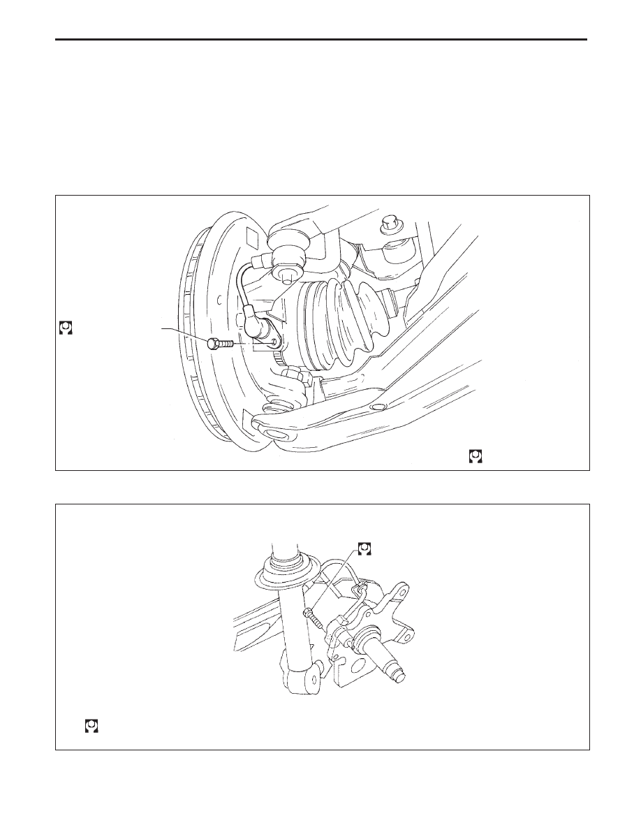
FRONT WHEEL SENSOR

REAR WHEEL SENSOR

NBR176

18 - 24 (1.8 - 2.4, 13 - 18)

: N·m (kg-m, ft-lb)

NBR296

: N·m (kg-m, ft-lb)

25 - 33
(2.6 - 3.4, 18 - 24)

ANTI-LOCK BRAKE SYSTEM

BR-53

SENSOR ROTOR

Removal

1. Remove the drive shaft and rear wheel hub. Refer to FA, RA

section (“Drive Shaft”, FRONT AXLE” and “Wheel Hub”,
REAR AXLE”).

2. Remove the sensor rotor using suitable puller, drift and bear-

ing replacer.

Installation

Install the sensor rotor. For front sensor rotor, use hammer and
wooden block. For rear sensor rotor, use suitable drift and press.

Always replace sensor rotor with new one.

Ensure sensor rotor is completely flush with surface indicated
on drive shaft.

Pay attention to the flush position of rear sensor rotor as
shown in figure.

h: −0.3 to +0.3 mm (−0.012 to +0.012 in)

CONTROL UNIT

Location: Built-in ABS actuator.
When disconnecting the harness connector, pull the lever
as shown figure.

SBR984C

Front sensor rotor

Drive shaft

SBR873CA

Rear sensor rotor

Suitable drift

NBR196

Front sensor rotor

Wooden
block

Flush

.

NBR197

Rear sensor rotor

Press

Suit-
able
drift

Sensor
rotor

Wheel hub

h

NBR261

ABS control unit
harness connector

ABS control unit

ABS actuator

X

1

X

PULL

ANTI-LOCK BRAKE SYSTEM

Removal and Installation (Cont’d)

BR-54

ABS ACTUATOR

NBR262

Front master cylinder secondary

To rear wheel cylinder (LH)

To rear wheel cylinder (RH)

Actuator/ground cable

10.8 - 14.7
(1.1 - 1.5,8.0 - 10.8)

: N·m (kg-m, in-lb)

: N·m (kg-m, ft-lb)

Actuator bracket

7 - 9
(0.7 - 0.9, 5.1 - 6.5)

ABS actuator & electric control
unit

11 - 15 (1.1 - 1.5, 8.0 -10.8)

To front wheel cylinder (RH)

To front wheel cylinder (LH)

From master cylinder primary

10 - 14 (1.0 - 1.4, 7.2 - 10.1)

FRONT

Lock

Unlock

ANTI-LOCK BRAKE SYSTEM

Removal and Installation (Cont’d)

BR-55

1. Disconnect battery cable.
2. Drain brake fluid. Refer to BR-7

3. Unlock the slider then disconnect the electrical harness con-

nectors from ABS control unit.

4. Identify each brake pipe with corresponding actuator port

hole and mark them accordingly.

5. Disconnect brake pipes and move them away from actuator.

Do not force brake pipes so as to kink them or bend them
excessively.
Ensure that brake fluid does not come into contact with
any parts.

6. Loosen/remove

mounting

nuts

between

actuator

and

bracket.

CAUTION:

After installation, pay attention to the following points:

Refill brake fluid and bleed air. Refer to “CHECK AND
ADJUSTMENT”,

BR-7

and

“BLEEDING

BRAKE

SYSTEM”, BR-8, respectively.

The installation procedure is as follows:

1. Install actuator on bracket without tightening fixings.
2. Assemble brake tubes to actuator without tightening tube

nuts. Ensure that correct tubes are connected to each port.

3. Fully tighten actuator and bracket fixings to specified torque.
4. Fully tighten flare nuts to specified torque, BR-10.
5. Secure ABS control unit harness connector and battery

cable.

NBR261

ABS control unit har-
ness connector

ABS control unit

ABS actuator

PULL

NBR249

NBR171

ABS actuator

.

10.8 - 14.7 N·m
(1.1 - 1.5 Kg-m,
8.0 - 10.8 ft-lb)

ANTI-LOCK BRAKE SYSTEM

Removal and Installation (Cont’d)

BR-56


Content   ..  42  43  44  45   ..