Nissan Primera P11. Manual - part 34


  Index      Nissan     Nissan Primera P11 (2001 year) - Service and Repair Manual


Search            


Content   ..  32  33  34  35   ..


Nissan Primera P11. Manual - part 34


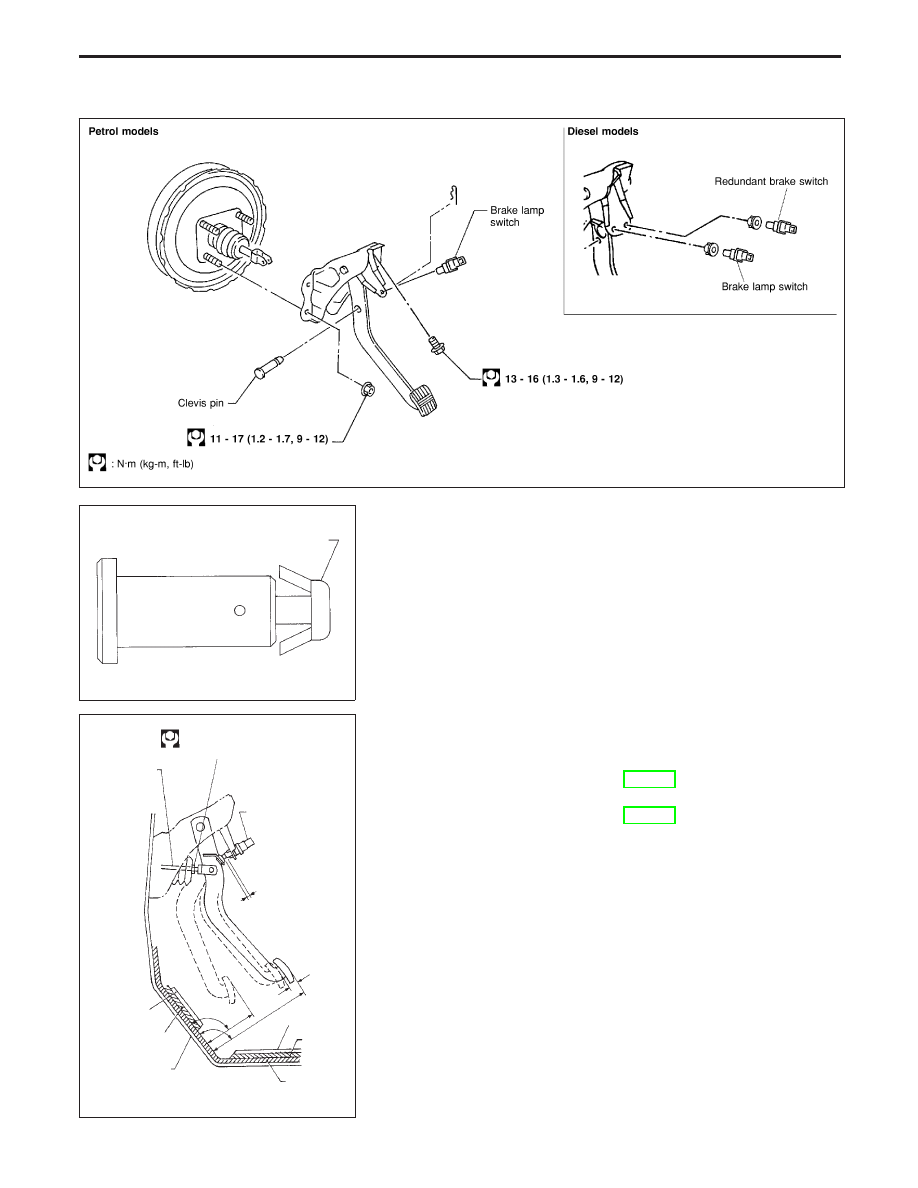
Removal and Installation

Inspection

Check brake pedal for following items:

Brake pedal bend

Clevis pin deformation

Crack of any welded portion

Crack or deformation of clevis pin stopper.

Adjustment

Check brake pedal free height from dash reinforcement panel.

H:

Free height

Refer to SDS, BR-92.

D:

Depressed height

Refer to SDS, BR-92.

C

1

, C

2

: Clearance between pedal stopper rubber and

threaded end of brake lamp switch (or redun-
dant brake switch).

0.75 - 2.0 mm (0.03 - 0.08 in)

A:

Pedal free play

1 - 3 mm (0.039 - 0.118 in)

NBR435

SBR997

Stopper

SBR110B

Clevis lock nut

16 - 22 N·m
(1.6 - 2.2 kg-m, 12 - 16 ft-lb)

Input rod

Brake lamp switch
and redundant
brake switch

C

1

or C

2

A

H

D

90°

Floor carpet

Dash insulator

Floor panel

Floor carpet

Dash
insulator

Melt sheet

BRAKE PEDAL AND BRACKET

BR-13

1. Loosen lock nut and adjust pedal free height by turning brake

booster input rod. Then tighten lock nut.

2. Check pedal free play.
Make sure that brake lamps go off when pedal is released.
3. Check brake pedal’s depressed height while engine is run-

ning.
If depressed height is below specified value, check brake
system for leaks, accumulation of air or any damage to com-
ponents (master cylinder, wheel cylinder, etc.); then make
necessary repairs.

SBR229E

Stays inside

Clevis

Lock nut

Input rod

BRAKE PEDAL AND BRACKET

Adjustment (Cont’d)

BR-14

Removal

1.

Reservoir cap

2.

Oil filter

3.

Reservoir tank

4.

Seal

5.

Cylinder body

6.

Elastic pin

7.

Piston stopper pin

8.

Secondary piston assembly

9.

Primary piston assembly

10. Circlip

CAUTION:

Be careful not to splash brake fluid on painted areas; it may
cause paint damage. If brake fluid is splashed on painted
areas, wash it away with water immediately.
1. Disconnect fluid level connector.
2. Connect a vinyl tube to air bleeder valve.
3. Drain brake fluid from each air bleeder valve, depressing

brake pedal to empty fluid from master cylinder.

4. Remove brake pipe flare nuts.
5. Remove master cylinder mounting nuts.

Disassembly

1. Drive out elastic pin from cylinder body.
2. Remove reservoir tank and seals.

NBR436

SBR231E

MASTER CYLINDER

BR-15

3. Remove the circlip with suitable pliers while piston is pushed

into cylinder.

4. Remove piston stopper pin while piston is pushed into cylin-

der.

5. Remove piston assemblies.

If it is difficult to remove secondary piston assembly,
gradually apply compressed air through fluid outlet.

Inspection

Check for the following items.
Replace any part if damaged.
Master cylinder:

Pin holes or scratches on inner wall.

Piston:

Deformation of or scratches on piston cups.

Assembly

1. Insert secondary piston assembly. Then insert primary piston

assembly.

Pay attention to alignment of secondary piston slit with
valve stopper mounting hole of cylinder body.

2. Install piston stopper pin while piston is pushed into cylinder.

Then secure the primary and secondary piston assemblies
with new circlip.

3. Push reservoir tank seals and reservoir tank into cylinder

body.

4. Install elastic pin.

NBR353

Push

Piston stop-
per pin

SBR232E

Secondary piston

Primary piston

SBR233E

Push

Piston stop-
per pin

SBR232E

MASTER CYLINDER

Disassembly (Cont’d)

BR-16


Content   ..  32  33  34  35   ..