Index Nissan Nissan Primera P11 (2001 year) - Service and Repair Manual
Search
Content .. 31 32 33 34 ..
Nissan Primera P11. Manual - part 33
NBR434
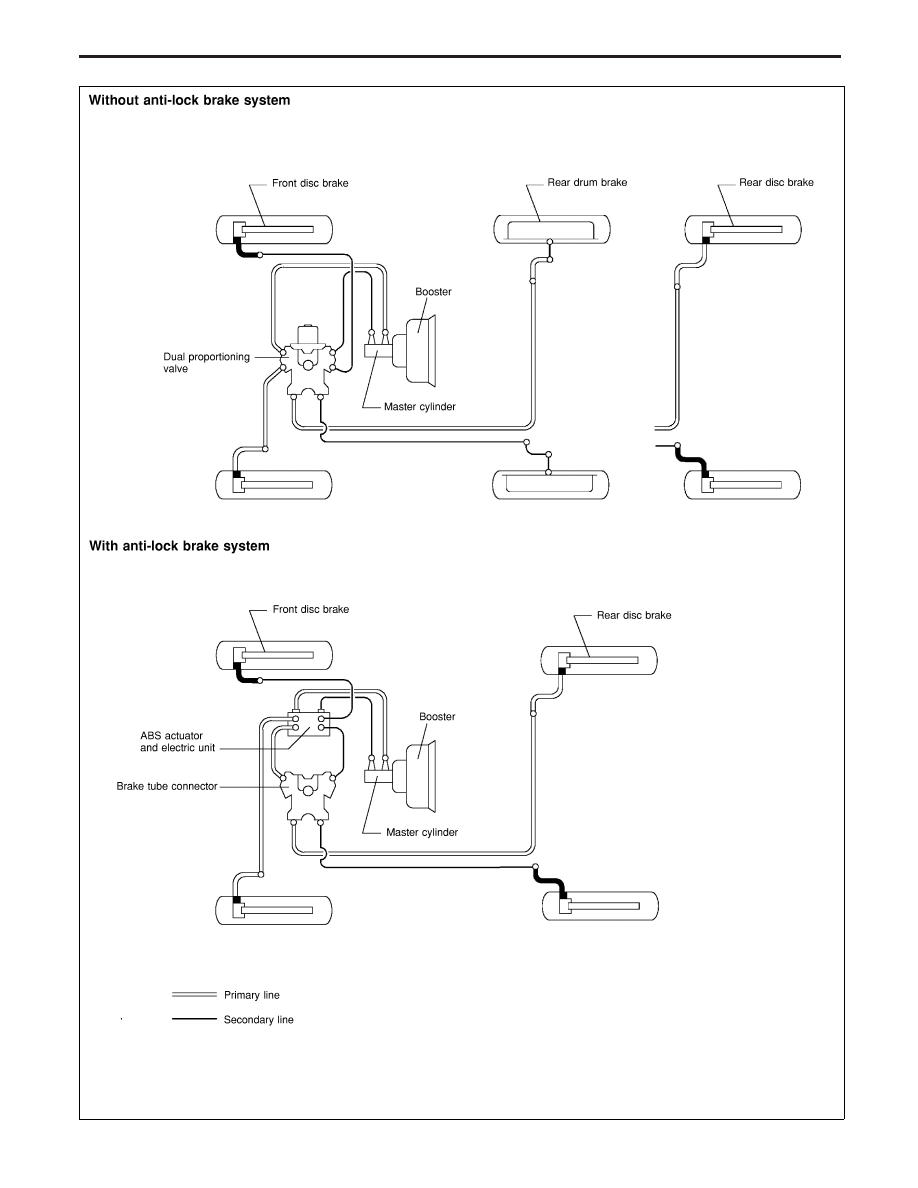
BRAKE HYDRAULIC LINE
BR-9