Nissan Frontier D22. Manual - part 935


  Index      Nissan     Nissan Frontier D22 Pickup (1998-2004 year) - Service and Repair Manual


Search            


Content   ..  933  934  935  936   ..


Nissan Frontier D22. Manual - part 935


WT-4

WHEEL

WHEEL

PFP:40300

Inspection

EES000XS

1.

Check tires for wear and improper inflation.

2.

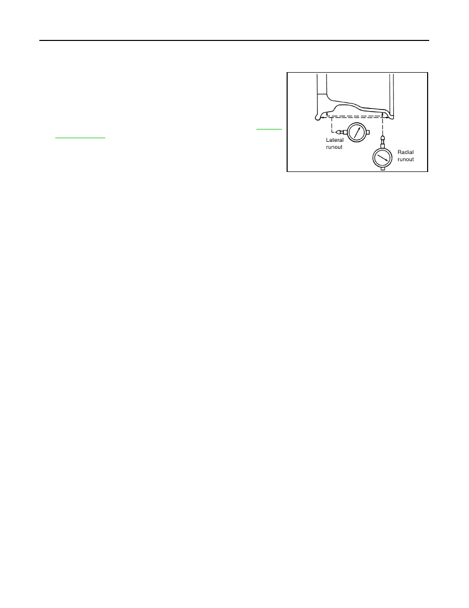
Check wheels for deformation, cracks and other damage. If
deformed, remove wheel and check wheel runout.

a.

Remove tire from wheel and mount wheel on a tire balance
machine.

b.

Set dial indicator as shown in the illustration. Refer to 

WT-25,

"Road Wheel"

 .

3.

Check front wheel bearings for looseness.

4.

Check front suspension for looseness.

SFA975B

WHEEL AND TIRE ASSEMBLY

WT-5

C

D

F

G

H

I

J

K

L

M

A

B

WT

WHEEL AND TIRE ASSEMBLY

PFP:40300

Balancing Wheels

EES000XT

REMOVAL

1.

Remove inner and outer balance weights from the wheel.

CAUTION:

Be careful not to scratch the wheel during removal.

2.

Using releasing agent, remove double-faced adhesive tape from the wheel.

CAUTION:

Be careful not to scratch the wheel during removal.

After removing double-faced adhesive tape, wipe clean traces of releasing agent from the
wheel.

WHEEL BALANCE ADJUSTMENT

If a tire balance machine has adhesion balance weight mode settings and drive-in weight mode setting,
select and adjust a drive-in weight mode suitable for wheels.

1.

Set wheel on wheel balancer using the center hole as a guide. Start the tire balance machine.

2.

When inner and outer imbalance values are shown on the wheel balancer indicator, multiply outer imbal-
ance value by 1.6 to determine balance weight that should be used. Select the outer balance weight with
a value closest to the calculated value and install it to the designated outer position of, or at the desig-
nated angle in relation to the road wheel.

CAUTION:

Do not install the inner balance weight before installing the outer balance weight.

Before installing the balance weight, be sure to clean the mating surface of the wheel.

Indicated imbalance value 

× 5/3 = balance weight to be installed

Calculation example:
23 g (0.81 oz) 

× 5/3 = 38.33 g (1.35 oz) = 40 g (1.41 oz) balance

weight (closer to calculated balance weight value)
Note that balance weight value must be closer to the calculated
balance weight value.
Example:
37.4 g = 35 g (1.23 oz)
37.5 g = 40 g (1.41 oz)

SMA054D

WT-6

WHEEL AND TIRE ASSEMBLY

a.

Install balance weight in the position shown.

b.

When installing balance weight to wheels, set it into the grooved
area on the inner wall of the wheel as shown so that the balance
weight center is aligned with the wheel balancer indication posi-
tion (angle).

CAUTION:

Always use genuine Nissan adhesion balance weights.

Balance weights are not reusable; always replace with
new ones.

Do not install more than three sheets of balance weights.

c.

If calculated balance weight value exceeds 50 g (1.76 oz), install
two balance weight sheets in line with each other as shown.

CAUTION:

Do not install one balance weight sheet on top of another.

3.

Start wheel balancer again.

4.

Install drive-in balance weight on inner side of road wheel in the
wheel balancer indication position (angle).

CAUTION:

Do not install more than two balance weights.

5.

Start wheel balancer. Make sure that inner and outer residual
imbalance values are 10 g (0.35 oz) each or below.

If either residual imbalance value exceeds 10 g (0.35 oz), repeat installation procedures.

Wheel balance (Maximum allowable imbalance):

Rotation

EES000XU

Follow the maintenance schedule for tire rotation service intervals. Refer to 

MA-7, "PERIODIC MAINTE-

NANCE"

 .

Do not include the T-type spare tire when rotating the tires.

CAUTION:

When installing wheels, tighten them diagonally by dividing
the work two to three times in order to prevent the wheels
from developing any distortion.

SMA055D

Maximum allowable 
imbalance

Dynamic (At rim flange)

10 g (0.35 oz) (one side)

Static

20 g (0.71 oz)

SMA056D

SMA829C

Tightening torque of wheel nut

: 118 - 147 N·m (12 - 15 kg-m, 87 - 108 ft-lb)

LOW TIRE PRESSURE WARNING SYSTEM

WT-7

C

D

F

G

H

I

J

K

L

M

A

B

WT

LOW TIRE PRESSURE WARNING SYSTEM

PFP:40300

System Components

EES000XV

System Description

EES000XW

TRANSMITTER (PRESSURE SENSOR)

A transmitter (pressure sensor) integrated with a valve is installed on
each wheel and transmits a detected air pressure signal in the form
of a radio wave.

LEIA0027E

LEIA0028E


Content   ..  933  934  935  936   ..