Nissan Frontier D22. Manual - part 889


  Index      Nissan     Nissan Frontier D22 Pickup (1998-2004 year) - Service and Repair Manual


Search            


Content   ..  887  888  889  890   ..


Nissan Frontier D22. Manual - part 889


RFD-64

[H233B]

REAR FINAL DRIVE ASSEMBLY

ASSEMBLY OF DIFFERENTIAL CASE (NON LSD)
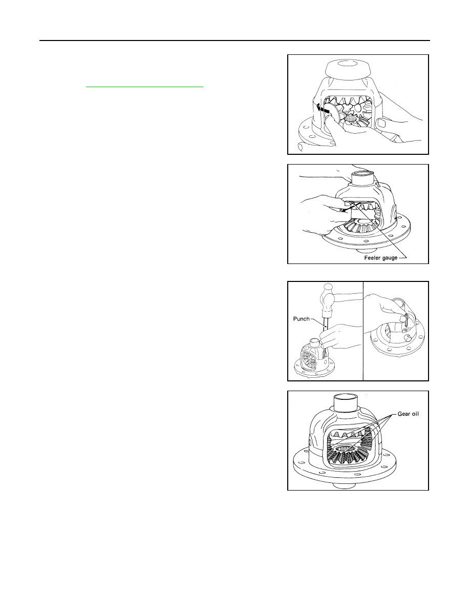
1.

Install side gears, pinion mate gears and thrust washers into dif-
ferential case.
The clearance can be adjusted with side gear thrust washer.
Refer to 

RFD-71, "Side Gear Adjustment"

 .

2.

Fit pinion mate shaft to differential case so that it meets lock pin-
holes.

3.

Adjust backlash between side gear and pinion mate gear by
selecting side gear thrust washer.

4.

 Install a new pinion mate shaft lock pin with a punch.

NOTE:

Always use a new lock pin.

Make sure lock pin is flush with case.

5.

Apply gear oil to gear tooth surfaces and thrust surfaces and
check to see that they turn properly.

6.

Install ring gear on differential case and tighten ring gear bolts.

Tighten bolts in a crisscross pattern.

SPD552

Backlash between side gear and 
pinion mate gear (Clearance 
between side gear thrust washer 
and differential case)

: 0.10 – 0.20 mm 
(0.0039 – 0.0079 in)

SPD258

SPD030

SPD322

Tool number

KV10112100 (BT-8653-A)

Ring gear bolts

Step 1

: 53.9 - 63.7 N·m (5.5 - 6.4 kg-m, 
40 - 46 lb-ft)

Step 2

: 34

° - 39° degrees rotation

REAR FINAL DRIVE ASSEMBLY

RFD-65

[H233B]

C

E

F

G

H

I

J

K

L

M

A

B

RFD

7.

Press-fit side bearing inner races on differential case with Tool.

ASSEMBLY OF DIFFERENTIAL CASE (WITH LSD)

Prior to assembling discs and plates, properly lubricate them by dipping them in limited slip differential oil.
Refer to 

MA-12, "RECOMMENDED FLUIDS AND LUBRICANTS"

 .

1.

Position specified number of friction plates, friction discs and
spacer on rear of side gear.

Always position a friction plate first on rear of side gear.

2.

Install two spring plates.

Tool number

A: ST33190000 (J-25523)

Tool number

B: ST33081000 (

)

PD244

No. of discs and plates (One side)

Friction disc

: 2

Friction plates

: 5

Spacer

: 1

SPD546A

SPD547A

RFD-66

[H233B]

REAR FINAL DRIVE ASSEMBLY

3.

Install friction plate guides.

Correctly align the raised portions of friction plates, and
apply LSD gear oil to inner surfaces of friction plate
guides to prevent them from falling.

4.

Install differential case B over side gear, discs, plates, spacer
and friction plate guide assembly.

Install differential case B while supporting friction plate guides
with your middle finger inserted through oil hole in differential
case.

Be careful not to detach spring plate from the hexagonal part
of the side gear.

5.

Install pinion mate gears and pinion mate thrust washers on pin-
ion mate shaft, then install pinion mate shaft in differential case
B.

6.

Install side gear to pinion mate gears.

7.

Install each disc and plate.

Use same procedures as outlined in steps 1 through 4 above.

8.

Install differential case A.

Position differential cases A and B by correctly aligning marks
stamped on cases.

SPD385A

SPD386A

SPD426

SPD387A

SPD388A

REAR FINAL DRIVE ASSEMBLY

RFD-67

[H233B]

C

E

F

G

H

I

J

K

L

M

A

B

RFD

9.

Tighten differential case couple bolts.

10. Place ring gear on differential case and tighten ring gear bolts.

Tighten bolts in a crisscross pattern.

11. Install side bearing inner race.

12. Check differential torque. Refer to 

RFD-54, "Checking Differential Torque"

 .

INSTALLATION OF DRIVE PINION ASSEMBLY

1.

Press-fit front and rear bearing outer races with Tools.

2.

Select drive pinion height adjusting washer. Refer to 

RFD-72,

"Drive Pinion Height Adjustment"

 .

3.

Install drive pinion adjusting washer in drive pinion, and press-fit
pinion rear bearing inner cone in it, with press and Tool.

Differential case couple 
bolts

: 64 - 74 N·m (6.5 - 7.5 kg-m, 
47 - 54 ft-lb)

Tool number

KV10112100 (BT-8653-A)

Ring gear bolts

Step 1

: 53.9 - 63.7 N·m (5.5 - 6.4 kg-m, 
40 - 46 lb-ft)

Step 2

: 34

° - 39° degrees rotation

SPD364A

Tool number

A: ST30611000 (J25742-1)

Tool number

B: ST30621000 (J25742-5)

Tool number

C: ST30613000 (J25742-3)

SPD580

Tool number

: ST30901000 (J-26010-01)

SPD377


Content   ..  887  888  889  890   ..