Nissan Frontier D22. Manual - part 838


  Index      Nissan     Nissan Frontier D22 Pickup (1998-2004 year) - Service and Repair Manual


Search            


Content   ..  836  837  838  839   ..


Nissan Frontier D22. Manual - part 838


MTC-74

REFRIGERANT LINES

Electronic Refrigerant Leak Detector

EJS0020S

PRECAUTIONS FOR HANDLING LEAK DETECTOR

NOTE:

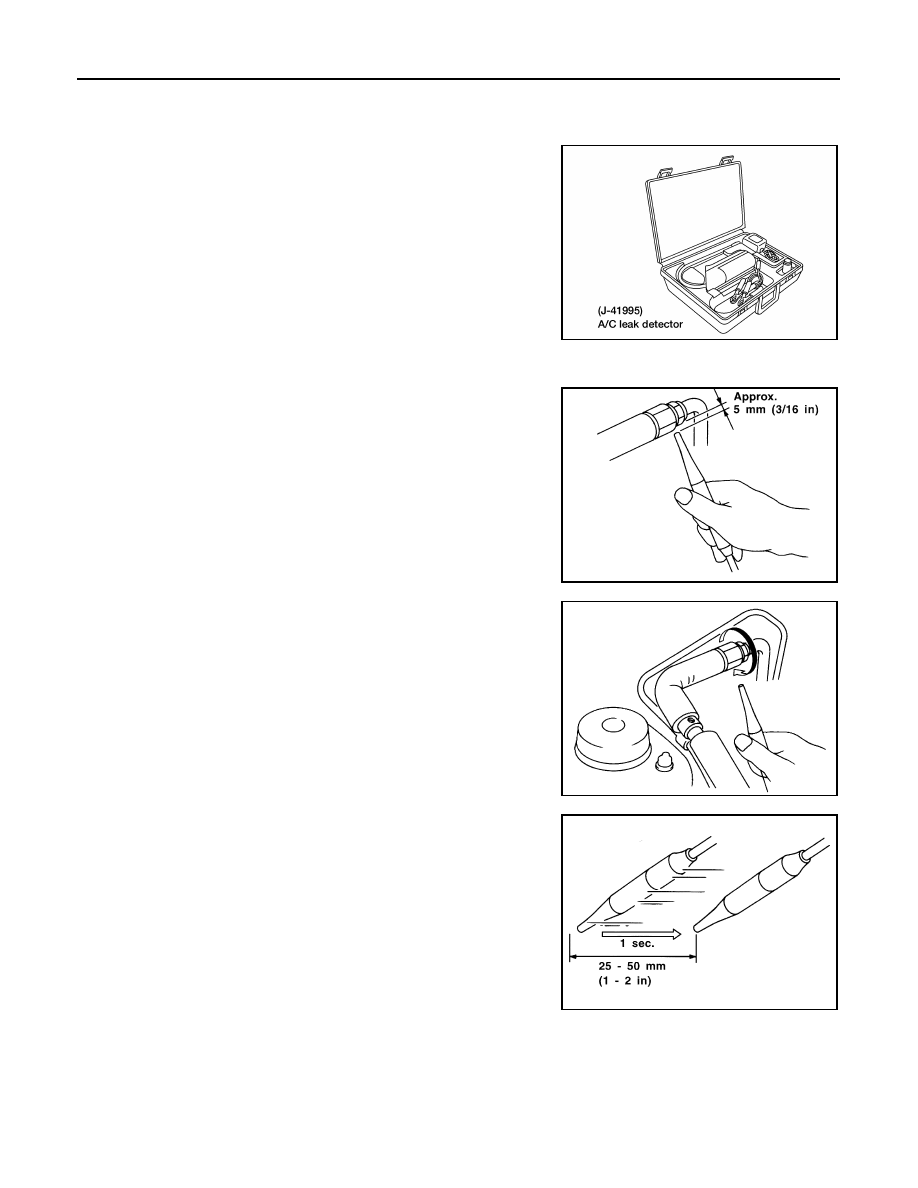
When performing a refrigerant leak check, use a J-41995 A/C
leak detector or equivalent. Ensure that the instrument is cali-
brated and set properly per the operating instructions.

The leak detector is a delicate device. In order to use the leak
detector properly, read the operating instructions and perform
any specified maintenance.

Other gases in the work area or substances on the A/C compo-
nents, for example, anti-freeze, windshield washer fluid, sol-
vents and lubricants, may falsely trigger the leak detector. Make
sure the surfaces to be checked are clean. Clean with a dry
cloth or blow off with shop air. 

Do not allow the sensor tip of the detector to contact any sub-
stance. This can also cause false readings and may damage the detector.

1.

Position probe approximately 5 mm (3/16 in) away from point to
be checked.

2.

When testing, circle each fitting completely with probe.

3.

Move probe along component approximately 25 - 50 mm (1 - 2
in)/sec.

CHECKING PROCEDURE

NOTE:
To prevent inaccurate or false readings, make sure there is no refrigerant vapor, shop chemicals or smoke in
the vicinity of the vehicle. Perform the leak test in a calm area (low air/wind movement) so that the leaking
refrigerant is not dispersed.
1.

Turn engine off.

AHA535A

SHA707EA

SHA706E

SHA708EA

REFRIGERANT LINES

MTC-75

C

D

E

F

G

H

I

K

L

M

A

B

MTC

2.

Connect a suitable A/C manifold gauge set to the A/C service ports.

3.

Check if the A/C refrigerant pressure is at least 345 kPa (3.52 kg/cm

2

 , 50 psi) above 16

°C (61°F). If less

than specification, recover/evacuate and recharge the system with the specified amount of refrigerant.
Refer to 

MTC-64, "HFC-134a (R-134a) Service Procedure"

 .

NOTE:
At temperatures below 16

°C (61°F), leaks may not be detected since the system may not reach 345 kPa

(3.52 kg/cm

2

 , 50 psi).

4.

Conduct the leak test from the high side (compressor discharge a  to evaporator f ) to the low side (evap-
orator drain hose g  to compressor suction k ). Refer to “

MTC-66, "Components"

 . Perform a leak check

for the following areas carefully. Clean the component to be checked and move the leak detector probe
completely around the connection/component.

Compressor
Check the fitting of high and low pressure hoses, relief valve and shaft seal.

Liquid tank
Check the pressure switch, tube fitting, weld seams and the fusible plug mounts.

Service valves
Check all around the service valves. Ensure service valve caps are secured on the service valves (to
prevent leaks).

NOTE:
After removing A/C manifold gauge set from service valves, wipe any residue from valves to prevent
any false readings by leak detector.

Cooling unit (evaporator)
With engine OFF, turn blower fan on “High” for at least 15 seconds to dissipate any refrigerant trace in
the cooling unit. Wait a minimum of 10 minutes accumulation time (refer to the manufacturer's recom-
mended procedure for actual wait time) before inserting the leak detector probe into the drain hose.
(Keep the probe inserted for at least ten seconds.) Use caution not to contaminate the probe tip with
water or dirt that may be in the drain hose.

5.

If a leak detector detects a leak, verify at least once by blowing compressed air into area of suspected
leak, then repeat check as outlined above.

6.

Do not stop when one leak is found. Continue to check for additional leaks at all system components and
connection.
If no leaks are found, perform steps 7 through 10.

7.

Start engine.

8.

Set the heater A/C control as follows:

a.

A/C switch ON

b.

Face mode

c.

Recirculation switch ON

d.

Max cold temperature

e.

Fan speed high

9.

Run engine at 1,500 rpm for at least 2 minutes.

10. Turn engine off and perform leak check again following steps 4

through 6 above.

Refrigerant leaks should be checked immediately after stop-
ping the engine. Begin with the leak detector at the compres-
sor. The pressure on the high pressure side will gradually
drop after refrigerant circulation stops and pressure on the
low pressure side will gradually rise, as shown in the graph.
Some leaks are more easily detected when pressure is high.

11. Before connecting recovery/recycling equipment to vehicle,

check recovery/recycling equipment gauges. No refrigerant
pressure should be displayed. If pressure is displayed, recover
refrigerant from equipment lines and then check refrigerant
purity.

12. Confirm refrigerant purity in supply tank using recovery/recycling equipment and refrigerant identifier.

Refer to 

MTC-4, "Contaminated Refrigerant"

 .

SHA839E

MTC-76

REFRIGERANT LINES

13. Confirm refrigerant purity in vehicle A/C system using recovery/recycling equipment and refrigerant identi-

fier. Refer to 

MTC-4, "Contaminated Refrigerant"

 .

14. Discharge A/C system using approved refrigerant recovery equipment. Refer to 

MTC-64, "Discharging

Refrigerant"

 . Repair the leaking fitting or component as necessary.

15. Evacuate and recharge A/C system. Refer to 

MTC-64, "Evacuating System and Charging Refrigerant"

 .

Perform the leak test to confirm no refrigerant leaks.

16. Conduct A/C performance test to ensure system works properly.

SERVICE DATA AND SPECIFICATIONS (SDS)

MTC-77

C

D

E

F

G

H

I

K

L

M

A

B

MTC

SERVICE DATA AND SPECIFICATIONS (SDS)

PFP:00030

General Specifications

EJS0020T

COMPRESSOR

LUBRICANT

*: Always check with the Parts Department for the latest parts information.

REFRIGERANT

Inspection and Adjustment

EJS0020U

ENGINE IDLING SPEED (WHEN A/C IS ON)

Refer to 

EC-36, "Idle Speed/Ignition Timing/Idle Mixture Ratio Adjustment"

  (KA24DE)

EC-604, "Idle

Speed/Ignition Timing/Idle Mixture Ratio Adjustment"

  (VG33E) or 

EC-1205, "Idle Speed/Ignition Timing/

Idle Mixture Ratio Adjustment"

  (VG33ER).

BELT TENSION

Refer to 

MA-15, "Checking Drive Belts"

  (KA24DE) or 

MA-24, "Checking Drive Belts"

    (VG33E  or

VG33ER).

MAGNET CLUTCH

Model

DKV-14C

Type

Vane rotary

Displacement

cm

3

  (cu in)/rev.

140 (8.54)

Direction of rotation

Clockwise (viewed from drive end)

Drive belt

A type

Model

ZEXEL make

DKV-14C

Name

Genuine NISSAN A/C System Lubricant

Type R or equivalent

Part No.*

KLH00–PAGR0

Capacity (total in system)

 m

 (US fl oz, Imp fl oz)

200 (6.8, 7.0)

Type

HFC 134a (R-134a)

Capacity

kg (lb)

0.60 - 0.70 (1.32 - 1.54)

g (oz)

600 - 700 (21.16 - 24.69)

Model

DKV-14C

Clutch disc-pulley clearance
mm (in)

0.3 - 0.6 (0.012 - 0.024)


Content   ..  836  837  838  839   ..