Nissan Frontier D22. Manual - part 819
MT-82
[FS5R30A]
SERVICE DATA AND SPECIFICATIONS (SDS)
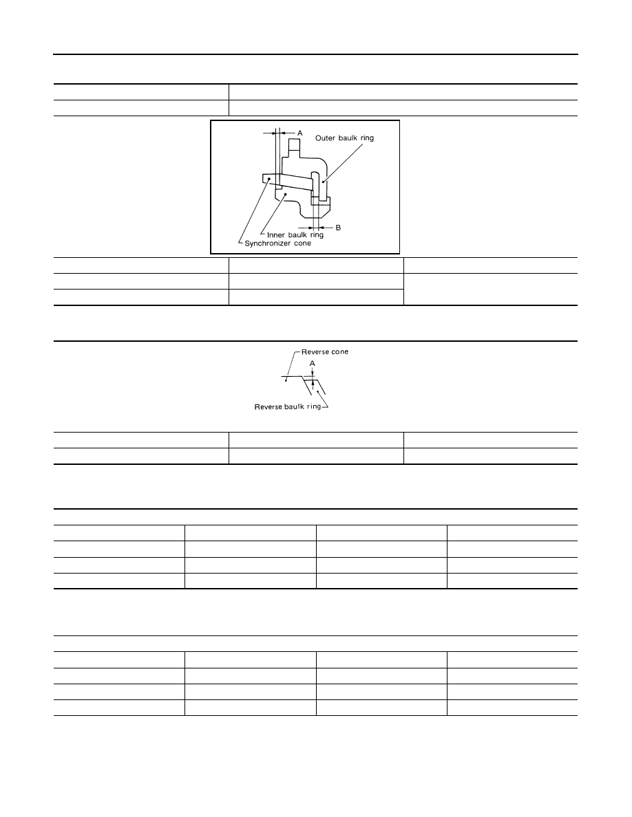
DOUBLE BAULK RING
Unit: mm (in)
Distance Between Rear Surface of Reverse Cone and Reverse Baulk Ring
ECS007ID
Unit: mm (in)
Available Snap Ring
ECS007IE
MAIN DRIVE GEAR SNAP RING
Unit: mm (in)
*Always check with the Parts Department for the latest parts information.
MAINSHAFT FRONT BEARING SNAP RING
Unit: mm (in)
*Always check with the Parts Department for the latest parts information.
VG33E model
2nd & 3rd baulk rings
VG33ER model
1st, 2nd & 3rd baulk rings
Dimension
Standard
Wear limit
A
0.7 - 0.9 (0.028 - 0.035)
0.2 (0.008)
B
0.6 - 1.1 (0.024 - 0.043)
SMT742C
Dimension
Standard
Wear limit
A
0.35 to 0.95 (0.0119 to 0.0295)
1.1 (0.043)
SMT428C
Main drive gear snap ring groove allowable clearance
0 - 0.1 (0 - 0.003)
Thickness
Part number*
Thickness
Part number*
1.89 (0.0744)
32204-01G60
2.03 (0.0799)
32204-01G63
1.95 (0.0768)
32204-01G61
2.07 (0.0815)
32204-01G64
1.99 (0.0783)
32204-01G62
2.11 (0.0831)
32204-01G65
Mainshaft front bearing snap ring groove allowable clearance
0 - 0.1 (0 - 0.003)
Thickness
Part number*
Thickness
Part number*
1.99 (0.0783)
32204-01G62
2.11 (0.0831)
32204-01G65
2.03 (0.0799)
32204-01G63
2.15 (0.0846)
32204-01G66
2.07 (0.0815)
32204-01G64
2.19 (0.0862)
32204-01G67