Nissan Frontier D22. Manual - part 747
GI-20
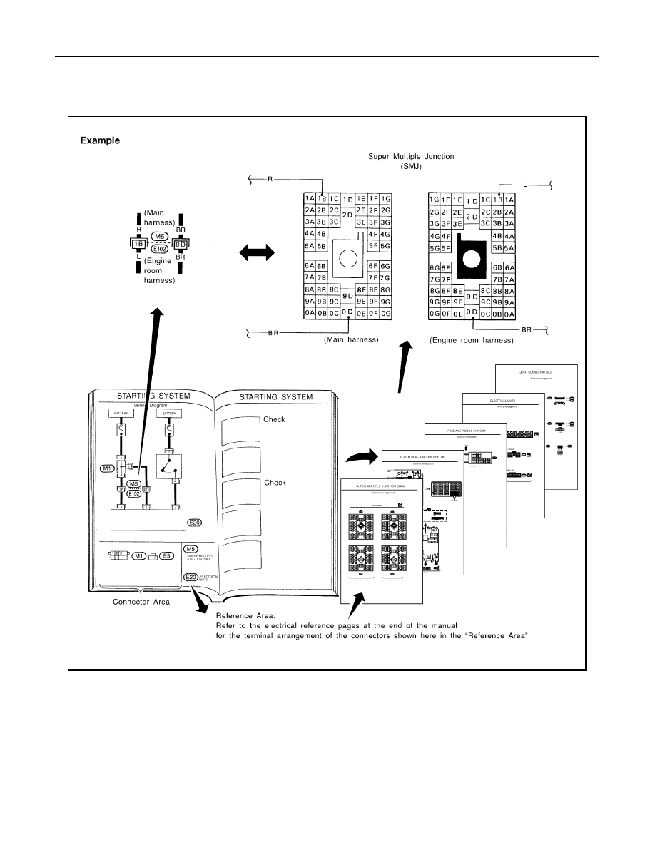
HOW TO USE THIS MANUAL
Reference Area
The Reference Area of the wiring diagram contains references to additional electrical reference pages at the
end of the manual. If connector numbers and titles are shown in the Reference Area of the wiring diagram,
these connectors symbols are not shown in the Connector Area.
●
SMJ (Super Multiple Junction)
In a wiring diagram, the SMJ connectors include a letter of the alphabet in the terminal number. SMJ con-
nector numbers are shown in the Reference Area of the wiring diagram. SMJ terminal arrangement can
be found on the electrical reference pages at the end of the manual. For terminal arrangement of these
connectors, refer to the “SMJ (SUPER MULTIPLE JUNCTION)” electrical reference page at the end of the
manual.
●
Fuse block—Junction Box (J/B)
Fuse block—Junction Box (J/B) connector number is shown in the Reference Area of the wiring diagram.
For connector terminal and fuse arrangement, refer to the “FUSE BLOCK—Junction Box (J/B)” electrical
reference page at the end of the manual.
SGI092A