Nissan Frontier D22. Manual - part 745
GI-12
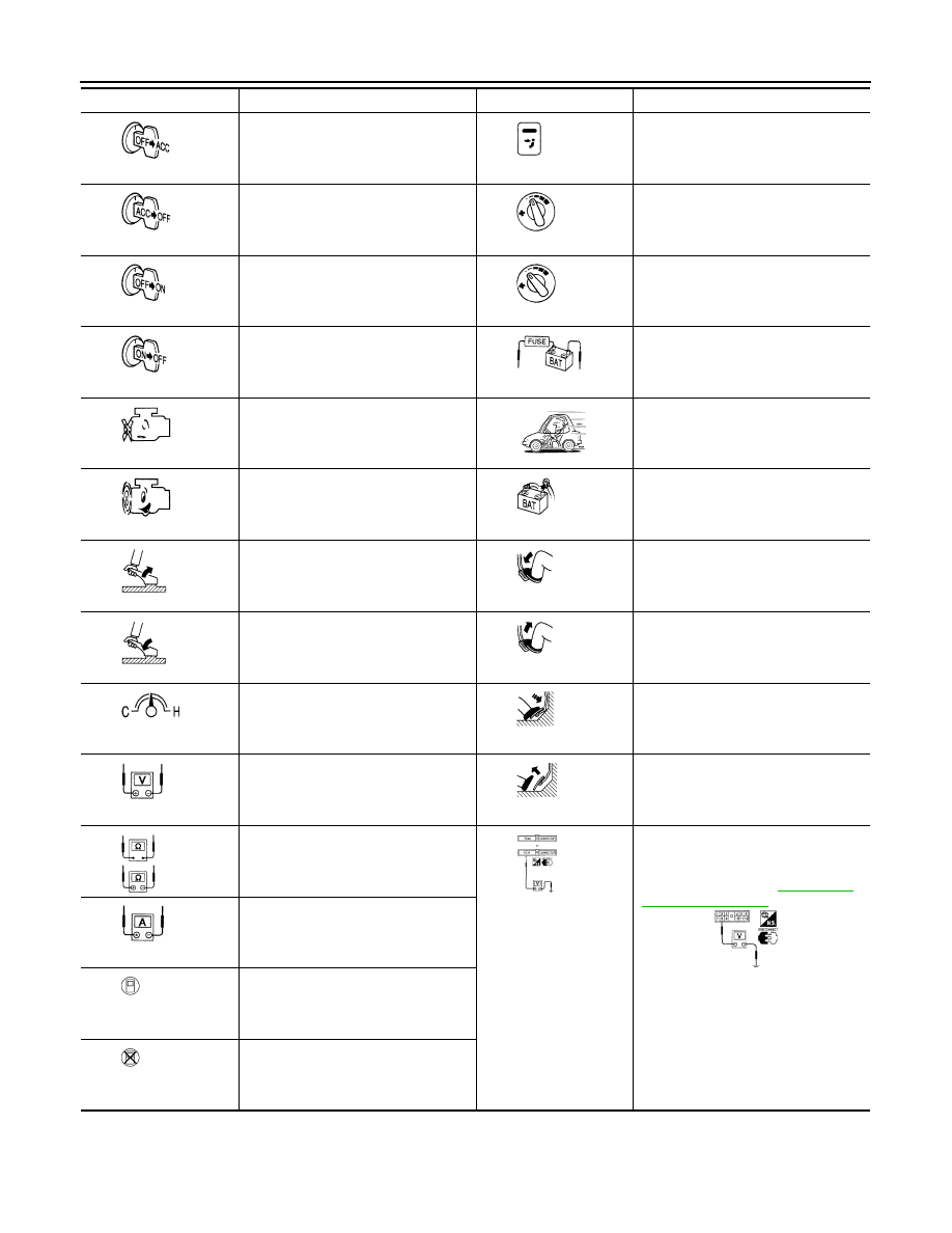
HOW TO USE THIS MANUAL
Turn ignition switch from OFF to ACC
position.
VENT switch is ON.
Turn ignition switch from ACC to OFF
position.
Fan switch is ON. (At any position
except for OFF position)
Turn ignition switch from OFF to ON
position.
Fan switch is OFF.
Turn ignition switch from ON to OFF
position.
Apply positive voltage from battery
with fuse directly to components.
Do not start engine, or check with
engine stopped.
Drive vehicle.
Start engine, or check with engine run-
ning.
Disconnect battery negative cable.
Apply parking brake.
Depress brake pedal.
Release parking brake.
Release brake pedal.
Check after engine is warmed up suffi-
ciently.
Depress accelerator pedal.
Voltage should be measured with a
voltmeter.
Release accelerator pedal.
Circuit resistance should be measured
with an ohmmeter.
Pin terminal check for SMJ type ECM
and TCM connectors.
For details regarding the terminal
arrangement, refer to
Current should be measured with an
ammeter.
Procedure with CONSULT-II
Procedure without CONSULT-II
Symbol
Symbol explanation
Symbol
Symbol explanation