Nissan Frontier D22. Manual - part 735
ON-VEHICLE SERVICE
FSU-15
C
D
F
G
H
I
J
K
L
M
A
B
FSU
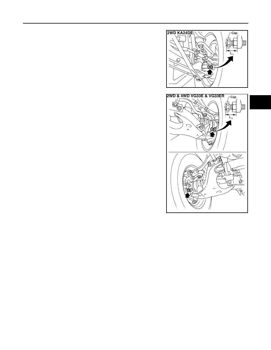
3.
Adjust stopper bolt if necessary.
Standard length “L
1
”
(2WD KA24DE model)
: 26.5 mm (1.043 in)
(Length before cap is
mounted)
ASU045
Standard length “L
2
”
(2WD and 4WD VG33E
and VG33ER models)
: Except P265/70R15 tire
26.5 mm (1.043 in)
(Length before cap is
mounted)
: P265/70R15 tire
30.0 mm (1.2 in)
(Length before cap is
mounted)
WSU019