Nissan Frontier D22. Manual - part 679


  Index      Nissan     Nissan Frontier D22 Pickup (1998-2004 year) - Service and Repair Manual


Search            


Content   ..  677  678  679  680   ..


Nissan Frontier D22. Manual - part 679


TIMING CHAIN

EM-23

[KA24DE]

C

D

E

F

G

H

I

J

K

L

M

A

EM

9.

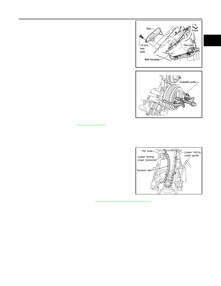
Remove the crankshaft bolt.  

If necessary, remove the rear plact and install Tool to prevent
crankshaft rotation.

10. Remove the crankshaft pulley with a suitable puller.

11. Remove the oil pan. Refer to 

EM-16, "Removal"

 .

12. Remove the oil pump, distributor drive shaft, and the oil pickup strainer.

13. Remove the front cover.

CAUTION:

Be careful not to tear or damage the cylinder head gasket.

14. Remove the following parts.

Release the timing chain tensioner by pushing the piston in
and inserting a suitable pin into the pin hole.

Chain tension arm

Lower timing chain guide

Air duct

15. Remove the upper timing chain. Refer to 

EM-21, "UPPER TIMING CHAIN"

 .

Tool number

:

(J-45499)

LBIA0364E

LEM115

SEM796E

EM-24

[KA24DE]

TIMING CHAIN

16. Wipe off the links of the timing chain next to the timing marks on

the sprockets. Put paint marks on the timing chain, matching
them with the timing marks on the crankshaft sprocket and idler
sprocket.

17. Remove the lower timing chain, crankshaft sprocket, and idler sprocket.

Inspection

EBS00GSC

Check for cracks and excessive wear at the roller links. Replace the
chain if necessary.

Installation

EBS00GSD

LOWER TIMING CHAIN

1.

Install crankshaft sprocket.

Make sure that the mating marks of crankshaft sprocket face
the front of the engine.

2.

Install the idler sprocket and lower timing chain using the mating marks and the paint marks made during
the removal process.

CAUTION:

Be careful not to tear or damage the cylinder head gasket.

AEM482

AEM403

SEM205C

TIMING CHAIN

EM-25

[KA24DE]

C

D

E

F

G

H

I

J

K

L

M

A

EM

3.

Install the chain guide and the chain tension arm.

4.

Install the lower chain tensioner and remove the pin securing the piston in the tensioner body.

5.

Install the front cover and oil seal.

Using a scraper or other suitable tool remove all traces of liq-
uid gasket from the cylinder block and front cover mating sur-
faces.

Install a new crankshaft seal in the front cover.

Apply a continuous bead of Genuine Silicone RTV Sealant or
equivalent, to the front cover. Refer to 

MA-12, "Recom-

mended Fluids and Lubricants"

 .

Install a new front oil seal using a suitable tool. Refer to 

EM-

28, "FRONT OIL SEAL"

 .

Apply Genuine Silicone RTV Sealant on the head gasket surface. Refer to 

GI-42, "RECOMMENDED

CHEMICAL PRODUCTS AND SEALANTS"

 .

Install the front engine cover.

6.

Install oil strainer and oil pan. Refer to 

EM-17, "Installation"

 .

7.

Install the oil pump and distributor drive shaft.

Make sure the flat side of the distributor drive shaft is facing
the engine. Failure to do so will result in the distributor being
out of time.

8.

Install the crankshaft pulley and crankshaft pulley bolt. Refer to

EM-13, "Removal and Installation"

 .

SEM796E

SEM715A

SEM292D

AEM391

EM-26

[KA24DE]

TIMING CHAIN

9.

If installed, remove Tool. 

10. Install the rear plate.

11. Install the A/C compressor and idler pulley bracket. Refer to 

MTC-67, "Removal and Installation for Com-

pressor"

 .

12. Install the radiator shroud and cooling fan with coupling. Refer to 

CO-14, "Removal and Installation"

 .

13. Install the A/C compressor, generator, and power steering pump drive belts. Refer to 

MA-15, "Checking

Drive Belts"

 .

14. Install the intake air duct.

IDLER SPROCKET

Install the lower timing chain. Refer to 

EM-24, "LOWER TIMING CHAIN"

 .

UPPER TIMING CHAIN

1.

Install the lower timing chain and idler sprocket. Refer to 

EM-24,

"LOWER TIMING CHAIN"

  an

EM-26, "IDLER SPROCKET"

 .

2.

Install the upper timing chain and sprockets, aligning the paint
marks made during removal as shown.

Tool number

:

(J-45499)

LBIA0364E

Rear plate bolts

10 mm hex

: 3 - 4 N·m (0.3 - 0.4 kg-m, 32 - 35 in-lb)

14 mm hex

: 16 - 22 N·m (1.6 - 2.2 kg-m, 12 - 16 ft-lb)

LBIA0363E

SEM548G

SEM549G


Content   ..  677  678  679  680   ..