Nissan Frontier D22. Manual - part 607


  Index      Nissan     Nissan Frontier D22 Pickup (1998-2004 year) - Service and Repair Manual


Search            


Content   ..  605  606  607  608   ..


Nissan Frontier D22. Manual - part 607


DTC P0453 EVAP CONTROL SYSTEM PRESSURE SENSOR

EC-1531

[VG33ER]

C

D

E

F

G

H

I

J

K

L

M

A

EC

4.

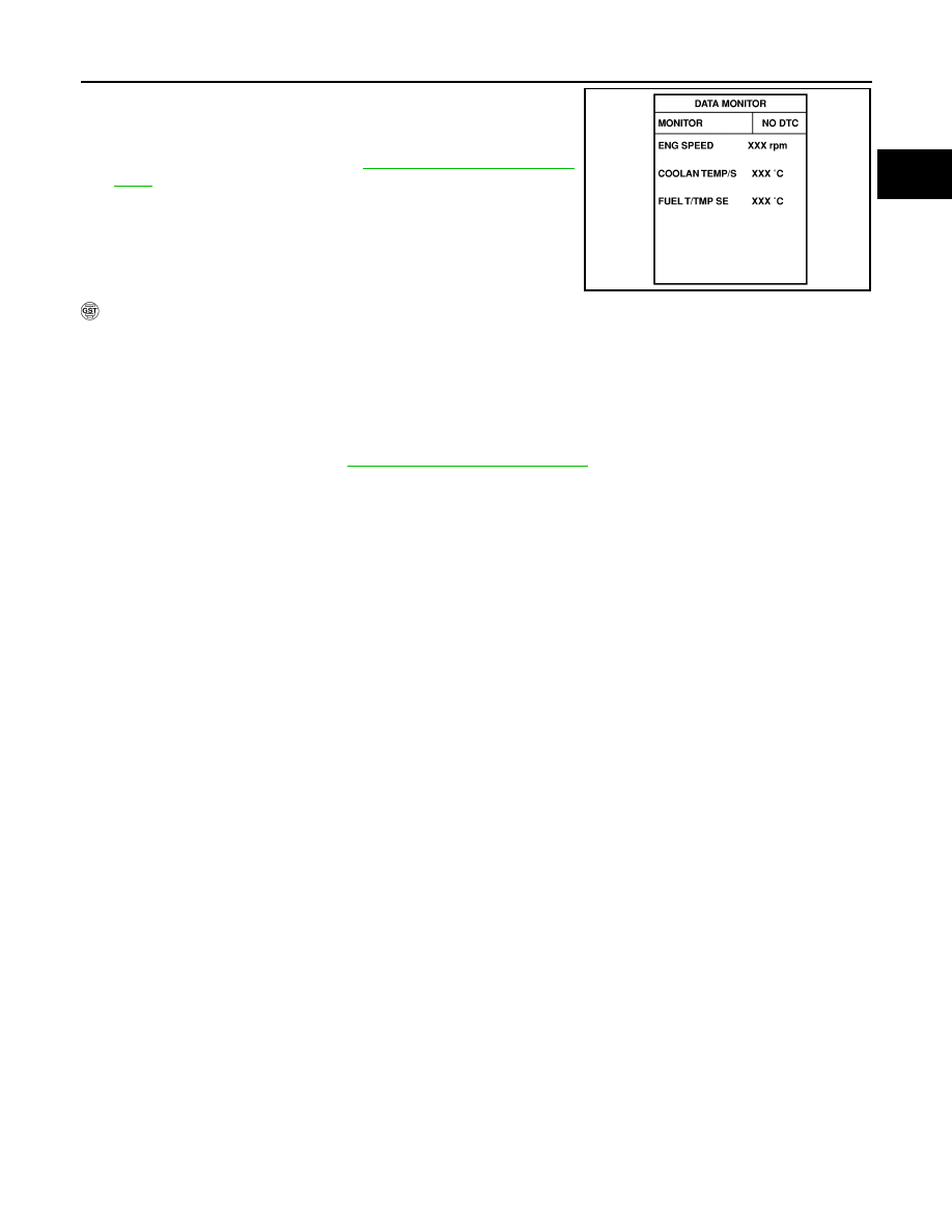
Select “DATA MONITOR” mode with CONSULT-II.

5.

Make sure that “FUEL T/TMP SE” is more than 0

°C (32°F).

6.

Start engine and wait at least 20 seconds.

7.

If 1st trip DTC is detected, go to 

EC-1533, "Diagnostic Proce-

dure"

 .

 WITH GST

1.

Start engine and warm it up to normal operating temperature.

2.

Check that voltage between ECM terminal 60 (Fuel tank temperature sensor signal) and ground is less
than 4.2V.

3.

Turn ignition switch OFF and wait at least 10 seconds.

4.

Start engine and wait at least 20 seconds.

5.

Select MODE 7 with GST.
If 1st trip DTC is detected, go to 

EC-1533, "Diagnostic Procedure"

 .

SEF194Y

EC-1532

[VG33ER]

DTC P0453 EVAP CONTROL SYSTEM PRESSURE SENSOR

Wiring Diagram

UBS00DY9

BBWA1087E

DTC P0453 EVAP CONTROL SYSTEM PRESSURE SENSOR

EC-1533

[VG33ER]

C

D

E

F

G

H

I

J

K

L

M

A

EC

Specification data are reference values and are measured between each terminal and ground.

CAUTION:

Do not use ECM ground terminals when measuring input/output voltage. Doing so may result in dam-
age to the ECM's transistor. Use a ground other than the ECM terminals, such as the ground.

Diagnostic Procedure

UBS00DYA

1. 

CHECK RUBBER TUBE

1.

Turn ignition switch OFF.

2.

Check rubber tube connected to the sensor for clogging, vent,
kink, disconnection or improper connection.

OK or NG

OK

>> GO TO 2.

NG

>> Reconnect, repair or replace.

2. 

RETIGHTEN GROUND SCREWS

1.

Loosen and retighten engine ground screws.

>> GO TO 3.

3. 

 CHECK CONNECTOR

1.

Disconnect EVAP control system pressure sensor harness connector.

2.

Check sensor harness connector for water.
Water should not exist.

OK or NG

OK

>> GO TO 4.

NG

>> Repair or replace harness connector.

TER-

MINAL 

NO.

WIRE 

COLO

R

ITEM

CONDITION 

DATA (DC Voltage)

42

B/W

Sensors' power supply

[Ignition switch: ON]

Approximately 5V

43

BR

Sensors' ground

[Engine is running]

Warm-up condition

Idle speed

Approximately 0V

62

Y

EVAP control system pres-
sure sensor

[Ignition switch: ON]

1.8 - 4.8V

AEC651A

BBIA0418E

EC-1534

[VG33ER]

DTC P0453 EVAP CONTROL SYSTEM PRESSURE SENSOR

4. 

CHECK EVAP CONTROL SYSTEM PRESSURE SENSOR POWER SUPPLY CIRCUIT

1.

Turn ignition switch ON.

2.

Check voltage between terminal 3 and ground with CONSULT-II
or tester.

OK or NG

OK

>> GO TO 6.

NG

>> GO TO 5.

5. 

DETECT MALFUNCTIONING PART

Check the following.

Harness connectors C1, M67

Harness connectors M81, F36

Harness for open or short between EVAP control system pressure sensor and ECM

>> Repair harness or connectors.

6. 

CHECK EVAP CONTROL SYSTEM PRESSURE SENSOR GROUND CIRCUIT FOR OPEN AND 

SHORT

1.

Turn ignition switch OFF.

2.

Check harness continuity between EVAP control system pressure sensor terminal 1 and engine ground.
Refer to Wiring Diagram.

3.

Also check harness for short to power.

OK or NG

OK >> GO 

TO 

8.

NG

>> GO TO 7.

7. 

DETECT MALFUNCTIONING PART

Check the following.

Harness connectors C1, M67

Harness connectors M59, F27

Harness for open or short between EVAP control system pressure sensor and ECM

>> Repair open circuit or short to power in harness or connectors.

Voltage: Approximately 5V

SEF889U

Continuity should exist.


Content   ..  605  606  607  608   ..