Nissan Frontier D22. Manual - part 605


  Index      Nissan     Nissan Frontier D22 Pickup (1998-2004 year) - Service and Repair Manual


Search            


Content   ..  603  604  605  606   ..


Nissan Frontier D22. Manual - part 605


DTC P0447 EVAP CANISTER VENT CONTROL VALVE

EC-1523

[VG33ER]

C

D

E

F

G

H

I

J

K

L

M

A

EC

6. 

DETECT MALFUNCTIONING PART

Check the following.

Harness connectors C1, M67

Harness connectors M81, F36

Harness for open or short between EVAP canister vent control valve and ECM

>> Repair open circuit or short to ground or short to power in harness or connectors.

7. 

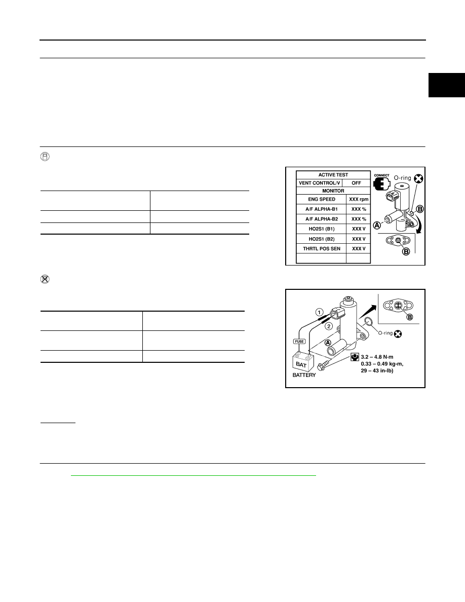
CHECK EVAP CANISTER VENT CONTROL VALVE

 With CONSULT-II

1.

Perform “VENT CONTROL/V” in “ACTIVE TEST” mode.

2.

Check air passage continuity and operation delay time.

Operation takes less than 1second.

 Without CONSULT-II 

1.

Check air passage continuity and operation delay time under the
following condition.

Operation takes less than 1 second.

If NG or operation takes more than 1 second, clean valve using air
blower or replace as necessary.
If portion B  is rusted, replace control valve.
Make sure new O-ring is installed properly.

OK or NG

OK >> GO 

TO 

8.

NG

>> Replace EVAP canister vent control valve.

8. 

CHECK INTERMITTENT INCIDENT

Refer to 

EC-1297, "TROUBLE DIAGNOSIS FOR INTERMITTENT INCIDENT"

 .

>> INSPECTION END.

Condition VENT CONTROL/V

Air passage continuity between 

A and B

ON

No

OFF

Yes

SEF013Z

Condition

Air passage continuity between A 

and B

12V direct current supply 
between terminals 1 and 2

No

OFF

Yes

BBIA0309E

EC-1524

[VG33ER]

DTC P0452 EVAP CONTROL SYSTEM PRESSURE SENSOR

DTC P0452 EVAP CONTROL SYSTEM PRESSURE SENSOR

PFP:25085

Component Description

UBS00DXZ

The EVAP control system pressure sensor detects pressure in the
purge line. The sensor output voltage to the ECM increases as pres-
sure increases. The EVAP control system pressure sensor is not
used to control the engine system. It is used only for on board diag-
nosis.

CONSULT-II Reference Value in Data Monitor Mode

UBS00DY0

Specification data are reference values.

On Board Diagnosis Logic

UBS00DY1

DTC Confirmation Procedure

UBS00DY2

NOTE:
If DTC Confirmation Procedure has been previously conducted, always turn ignition switch OFF and wait at
least 5 seconds before conducting the next test.
TESTING CONDITION:
Always perform test at a temperature of 5

°C (41°F) or more.

 WITH CONSULT-II

1.

Start engine and warm it up to normal operating temperature.

2.

Turn ignition switch OFF and wait at least 5 seconds.

3.

Turn ignition switch ON.

SEF340V

PBIB1207E

MONITOR ITEM

CONDITION

SPECIFICATION

EVAP SYS PRES

Ignition switch: ON

 1.8 - 4.8V

DTC No.

Trouble diagnosis name

DTC detecting condition

Possible cause

P0452

EVAP control system 
pressure sensor low 
input

An excessively low voltage from the sensor is 
sent to ECM.

Harness or connectors
(The sensor circuit is open or shorted.)

EVAP control system pressure sensor

DTC P0452 EVAP CONTROL SYSTEM PRESSURE SENSOR

EC-1525

[VG33ER]

C

D

E

F

G

H

I

J

K

L

M

A

EC

4.

Select “DATA MONITOR” mode with CONSULT-II.

5.

Make sure that “FUEL T/TMP SE” is more than 0

°C (32°F).

6.

Start engine and wait at least 20 seconds.

7.

If 1st trip DTC is detected, go to 

EC-1527, "Diagnostic Proce-

dure"

 .

 WITH GST

1.

Start engine and warm it up to normal operating temperature.

2.

Check that voltage between ECM terminal 60 (Fuel tank temperature sensor signal) and ground is less
than 4.2V.

3.

Turn ignition switch OFF and wait at least 10 seconds.

4.

Start engine and wait at least 20 seconds.

5.

Select MODE 7 with GST.
If 1st trip DTC is detected, go to 

EC-1527, "Diagnostic Procedure"

 .

SEF194Y

EC-1526

[VG33ER]

DTC P0452 EVAP CONTROL SYSTEM PRESSURE SENSOR

Wiring Diagram

UBS00DY3

BBWA1087E


Content   ..  603  604  605  606   ..