Nissan Frontier D22. Manual - part 608


  Index      Nissan     Nissan Frontier D22 Pickup (1998-2004 year) - Service and Repair Manual


Search            


Content   ..  606  607  608  609   ..


Nissan Frontier D22. Manual - part 608


DTC P0453 EVAP CONTROL SYSTEM PRESSURE SENSOR

EC-1535

[VG33ER]

C

D

E

F

G

H

I

J

K

L

M

A

EC

8. 

CHECK EVAP CONTROL SYSTEM PRESSURE SENSOR INPUT SIGNAL CIRCUIT FOR OPEN AND 

SHORT

1.

Disconnect ECM harness connector.

2.

Check harness continuity between ECM terminal 62 and EVAP control system pressure sensor terminal
2.
Refer to Wiring Diagram.

3.

Also check harness for short to ground and short to power.

OK or NG

OK >> GO 

TO 

10.

NG

>> GO TO 9.

9. 

DETECT MALFUNCTIONING PART

Check the following.

Harness connectors C1, M67

Harness connectors M59, F27

Harness for open or short between ECM and EVAP control system pressure sensor

>> Repair open circuit or short to ground or short to power in harness or connectors.

10. 

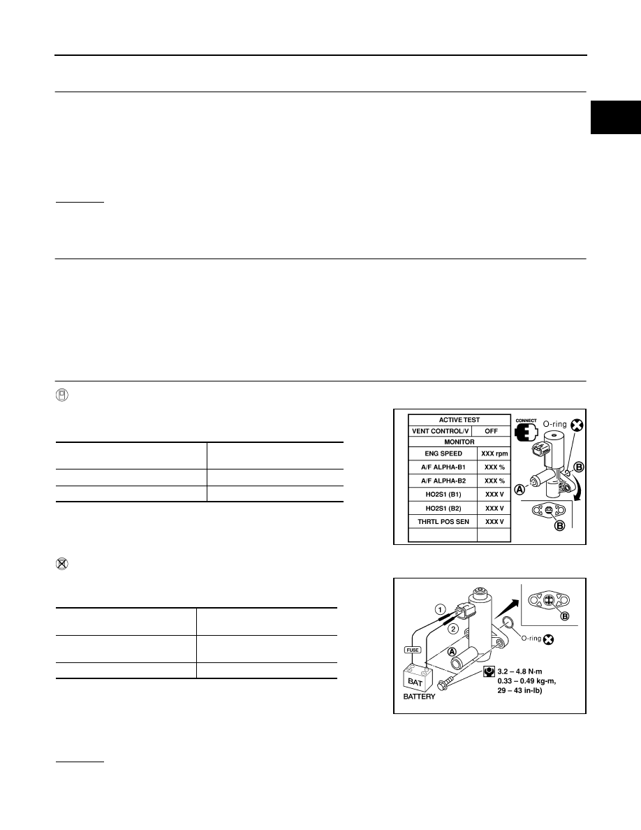
CHECK EVAP CANISTER VENT CONTROL VALVE

 With CONSULT-II

1.

Perform “VENT CONTROL/V” in “ACTIVE TEST” mode.

2.

Check air passage continuity and operation delay time.

Operation takes less than 1second.

 Without CONSULT-II 

1.

Check air passage continuity and operation delay time under the
following condition.

Operation takes less than 1 second.

If NG or operation takes more than 1 second, clean valve using air
blower or replace as necessary.
If portion B  is rusted, replace control valve.
Make sure new O-ring is installed properly.

OK or NG

OK

>> GO TO 11.

NG

>> Replace EVAP canister vent control valve.

Continuity should exist.

Condition VENT CONTROL/V

Air passage continuity between 

A and B

ON

No

OFF

Yes

SEF013Z

Condition

Air passage continuity between A 

and B

12V direct current supply 
between terminals 1 and 2

No

OFF

Yes

BBIA0309E

EC-1536

[VG33ER]

DTC P0453 EVAP CONTROL SYSTEM PRESSURE SENSOR

11. 

CHECK EVAP CONTROL SYSTEM PRESSURE SENSOR

1.

Remove EVAP control system pressure sensor with its harness connector connected.

2.

Remove hose from EVAP control system pressure sensor.

3.

Turn ignition switch ON. 

4.

Use pump to apply vacuum and pressure to EVAP control system pressure sensor as shown in figure.

5.

Check input voltage between ECM terminal 62 and ground.

CAUTION:

Always calibrate the vacuum pump gauge when using it.

Do not apply below 

93.3 kPa (700 mmHg, 27.56 inHg) or

over 101.3 kPa (760 mmHg, 29.92 inHg) of pressure.

OK or NG

OK

>> GO TO 12.

NG

>> Replace EVAP control system pressure sensor.

12. 

CHECK RUBBER TUBE

Check obstructed rubber tube connected to EVAP canister vent control valve.
OK or NG

OK

>> GO TO 13.

NG

>> Clean, repair or replace rubber tube.

13. 

CHECK WATER SEPARATOR

1.

Check visually for insect nests in the water separator air inlet.

2.

Check visually for cracks or flaws in the appearance.

3.

Check visually for cracks or flaws in the hose.

4.

Check that A  and C  are not clogged by blowing air into B  with
A , and then C  plugged. 

5.

In case of NG in items 2 - 4, replace the parts.

NOTE:

Do not disassemble water separator.

OK or NG

OK

>> GO TO 14.

NG

>> Replace water separator.

Applied vacuum

Voltage V

Not applied

1.8 - 4.8

−26.7 kpa (−200 mmHg, −7.87 inHg)

2.1 to 2.5 V lower than above value

PBIB1426E

PBIB1032E

DTC P0453 EVAP CONTROL SYSTEM PRESSURE SENSOR

EC-1537

[VG33ER]

C

D

E

F

G

H

I

J

K

L

M

A

EC

14. 

CHECK IF EVAP CANISTER SATURATED WITH WATER

1.

Remove EVAP canister with EVAP canister vent control valve attached.

2.

Check if water will drain from the EVAP canister.

Yes or No

Yes

>> GO TO 15.

 No

>> GO TO 17.

15. 

CHECK EVAP CANISTER

Weigh the EVAP canister with the EVAP canister vent control valve attached.
The weight should be less than 1.8 kg (4.0 lb).

OK or NG

OK

>> GO TO 17.

NG

>> GO TO 16.

16. 

DETECT MALFUNCTIONING PART

Check the following.

EVAP canister for damage

EVAP hose between EVAP canister and water separator for clogging or poor connection

>> Repair hose or replace EVAP canister.

17. 

CHECK INTERMITTENT INCIDENT

Refer to 

EC-1297, "TROUBLE DIAGNOSIS FOR INTERMITTENT INCIDENT"

 .

>> INSPECTION END.

SEF596U

EC-1538

[VG33ER]

DTC P0455 EVAP CONTROL SYSTEM

DTC P0455 EVAP CONTROL SYSTEM

PFP:14950

On Board Diagnosis Logic

UBS00DYB

NOTE:
If DTC P0455 is displayed with P1448, perform trouble diagnosis for DTC P1448 first. (

EC-1659

 .)

This diagnosis detects a very large leak (fuel filler cap fell off etc.) in EVAP system between the fuel tank and
EVAP canister purge volume control solenoid valve.

DTC No.

Trouble diagnosis name

DTC detecting condition

Possible cause

P0455

EVAP control system 
gross leak detected

EVAP control system has a very large leak 
such as fuel filler cap fell off, EVAP control sys-
tem does not operate properly.

Fuel filler cap remains open or fails to 
close.

Incorrect fuel tank vacuum relief valve

Incorrect fuel filler cap used

Foreign matter caught in fuel filler cap.

Leak is in line between intake manifold 
and EVAP canister purge volume control 
solenoid valve.

Foreign matter caught in EVAP canister 
vent control valve.

EVAP canister or fuel tank leaks

EVAP purge line (pipe and rubber tube) 
leaks

EVAP purge line rubber tube bent.

Blocked or bent rubber tube to EVAP 
control system pressure sensor

Loose or disconnected rubber tube

EVAP canister vent control valve and the 
circuit

EVAP canister purge volume control 
solenoid valve and the circuit

Fuel tank temperature sensor

O-ring of EVAP canister vent control 
valve is missing or damaged.

EVAP control system pressure sensor

Refueling control valve

ORVR system leaks

LEC086A


Content   ..  606  607  608  609   ..