Nissan Frontier D22. Manual - part 527


  Index      Nissan     Nissan Frontier D22 Pickup (1998-2004 year) - Service and Repair Manual


Search            


Content   ..  525  526  527  528   ..


Nissan Frontier D22. Manual - part 527


BASIC SERVICE PROCEDURE

EC-1211

[VG33ER]

C

D

E

F

G

H

I

J

K

L

M

A

EC

10. 

CHECK HEATED OXYGEN SENSOR 1 (BANK 2) SIGNAL

 With CONSULT-II

1.

Stop engine.

2.

Replace heated oxygen sensor 1 (bank 2).

3.

Start engine and warm it up to normal operating temperature.

4.

Run engine at approx. 2,000 rpm for approx. 2 minutes under no load.

5.

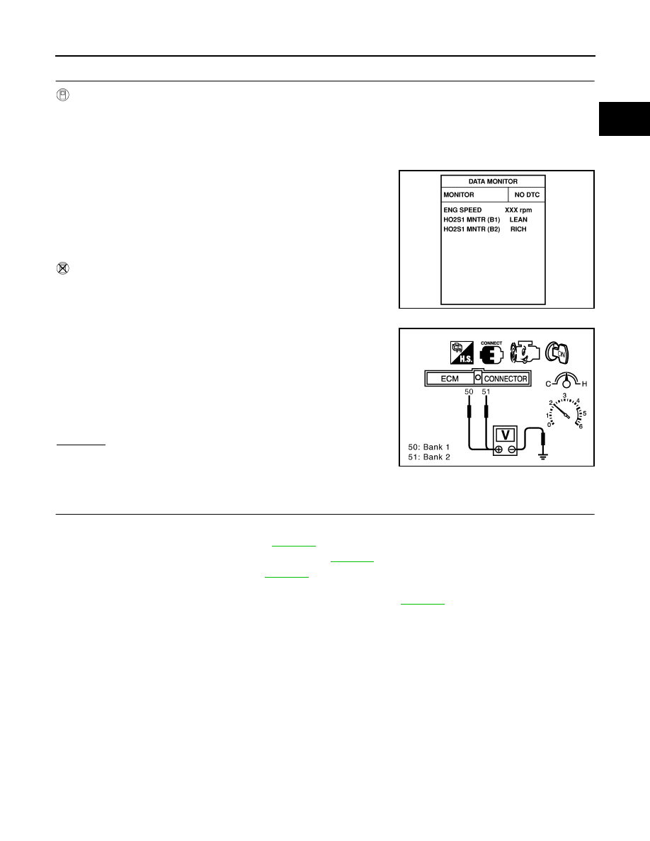
See “HO2S1 MNTR (B2)” in “DATA MONITOR” mode.

6.

Running engine at 2,000 rpm under no load (engine is warmed
up to normal operating temperature.), check that the monitor
fluctuates between “LEAN” and “RICH” more than 5 times dur-
ing 10 seconds.
1 time: RICH 

 LEAN  RICH

2 times: RICH 

 LEAN  RICH  LEAN  RICH

 Without CONSULT-II

1.

Stop engine.

2.

Replace heated oxygen sensor 1 (bank 2).

3.

Start engine and warm it up to normal operating temperature.

4.

Run engine at approx. 2,000 rpm for approx. 2 minutes under no
load.

5.

Set voltmeter probe between ECM terminal 51 and ground.

6.

Make sure that the voltage fluctuates between 0 - 0.3V and 0.6 -
1.0V more than 5 times during 10 seconds at 2,000 rpm.
1 time: 0 - 0.3V 

 0.6 - 1.0V  0 - 0.3V

2 times: 0 - 0.3V 

 0.6 - 1.0V  0 - 0.3V  0.6 - 1.0V  0 -

0.3V

OK or NG

OK (With CONSULT-II)>>GO TO 12.
OK (Without CONSULT-II)>>GO TO 13.
NG

>> GO TO 11.

11. 

DETECT MALFUNCTIONING PART

Check the following.

1.

Check fuel pressure regulator. Refer to 

EC-1219

 .

2.

Check mass air flow sensor and its circuit. Refer to 

EC-1327

 .

3.

Check injector and its circuit. Refer to 

EC-1716

 .

Clean or replace if necessary.

4.

Check engine coolant temperature sensor and its circuit. Refer to 

EC-1345

 .

5.

Check ECM function by substituting another known-good ECM.
(ECM may be the cause of an incident, but this is a rare case.)

>> GO TO 2.

PBIB0120E

PBIB2157E

EC-1212

[VG33ER]

BASIC SERVICE PROCEDURE

12. 

CHECK HEATED OXYGEN SENSOR 1 (BANK 1) SIGNAL

 With CONSULT-II

1.

See “HO2S1 (B1)” in “DATA MONITOR” mode.

2.

Maintaining engine at 2,000 rpm under no load (engine is
warmed up to normal operating temperature.), check that the
monitor fluctuates between “LEAN” and “RICH” more than 5
times during 10 seconds.

OK or NG

OK

>> INSPECTION END.

NG (Monitor does not fluctuate.)>>GO TO 16.
NG (Monitor fluctuates less than 5 times.)>>GO TO 14.

13. 

CHECK HEATED OXYGEN SENSOR 1 (BANK 1) SIGNAL

 Without CONSULT-II

1.

Set voltmeter probe between ECM terminal 50 and ground.

2.

Make sure that the voltage fluctuates between 0 - 0.3V and 0.6 -
1.0V more than 5 times during 10 seconds at 2,000 rpm.
1 time: 0 - 0.3V 

 0.6 - 1.0V  0 - 0.3V

2 times: 0 - 0.3V 

 0.6 - 1.0V  0 - 0.3V  0.6 - 1.0V  0 -

0.3V

OK or NG

OK

>> INSPECTION END.

NG (Voltage does not fluctuate.)>>GO TO 16.
NG (Voltage fluctuates less than 5 times.)>>GO TO 14.

1 time: RICH 

 LEAN  RICH

2 times: RICH 

 LEAN  RICH  LEAN  RICH

PBIB0120E

PBIB2157E

BASIC SERVICE PROCEDURE

EC-1213

[VG33ER]

C

D

E

F

G

H

I

J

K

L

M

A

EC

14. 

CHECK HEATED OXYGEN SENSOR 1 (BANK 1) SIGNAL

 With CONSULT-II

1.

Stop engine.

2.

Replace heated oxygen sensor 1 (bank 1).

3.

Start engine and warm it up to normal operating temperature.

4.

Run engine at approx. 2,000 rpm for approx. 2 minutes under no load.

5.

See “HO2S1 MNTR (B1)” in “DATA MONITOR” mode.

6.

Maintaining engine at 2,000 rpm under no-load (engine is
warmed up to normal operating temperature.), check that the
monitor fluctuates between “LEAN” and “RICH” more than 5
times during 10 seconds.
1 time: RICH 

 LEAN  RICH

2 times: RICH 

 LEAN  RICH  LEAN  RICH

 Without CONSULT-II

1.

Stop engine.

2.

Replace heated oxygen sensor 1 (bank 1).

3.

Start engine and warm it up to normal operating temperature.

4.

Run engine at approx. 2,000 rpm for approx. 2 minutes under no
load.

5.

Set voltmeter probe between ECM terminal 50 and ground.

6.

Make sure that the voltage fluctuates between 0 - 0.3V and 0.6 -
1.0V more than 5 times during 10 seconds at 2,000 rpm.
1 time: 0 - 0.3V 

 0.6 - 1.0V  0 - 0.3V

2 times: 0 - 0.3V 

 0.6 - 1.0V  0 - 0.3V  0.6 - 1.0V  0 -

0.3V

OK or NG

OK

>> INSPECTION END.

NG

>> GO TO 15.

15. 

DETECT MALFUNCTIONING PART

Check the following.

1.

Check fuel pressure regulator. Refer to 

EC-1219

 .

2.

Check mass air flow sensor and its circuit. Refer to 

EC-1327

 .

3.

Check injector and its circuit. Refer to 

EC-1716

 .

Clean or replace if necessary.

4.

Check engine coolant temperature sensor and its circuit. Refer to 

EC-1345

 .

5.

Check ECM function by substituting another known-good ECM.
(ECM may be the cause of an incident, but this is a rare case.)

>> GO TO 2.

PBIB0120E

PBIB2157E

EC-1214

[VG33ER]

BASIC SERVICE PROCEDURE

16. 

CHECK HEATED OXYGEN SENSOR 1 (BANK 1) HARNESS

1.

Stop engine and disconnect battery ground cable.

2.

Disconnect ECM harness connector.

3.

Disconnect heated oxygen sensor 1 (bank 1) harness connector.

4.

Check harness continuity between ECM terminal 50 and heated oxygen sensor 1 (bank 1) harness con-
nector.

OK or NG

OK

>> 1. Connect ECM harness connector.

2. GO TO 18.

NG

>> 1. Repair or replace harness.

2. GO TO 8 (With CONSULT-II).

GO TO 9 (Without CONSULT-II).

17. 

CHECK HEATED OXYGEN SENSOR 1 (BANK 2) HARNESS

1.

Stop engine and disconnect battery ground cable.

2.

Disconnect ECM harness connector.

3.

Disconnect heated oxygen sensor 1 (bank 2) harness connector.

4.

Check harness continuity between ECM terminal 51 and heated oxygen sensor 1 (bank 2) harness con-
nector.

OK or NG

OK

>> 1. Connect ECM harness connector.

2. GO TO 18.

NG

>> 1. Repair or replace harness.

2. GO TO 8 (With CONSULT-II).

GO TO 9 (Without CONSULT-II).

Continuity should exist.

Continuity should exist.


Content   ..  525  526  527  528   ..