Nissan Frontier D22. Manual - part 526


  Index      Nissan     Nissan Frontier D22 Pickup (1998-2004 year) - Service and Repair Manual


Search            


Content   ..  524  525  526  527   ..


Nissan Frontier D22. Manual - part 526


BASIC SERVICE PROCEDURE

EC-1207

[VG33ER]

C

D

E

F

G

H

I

J

K

L

M

A

EC

INSPECTION PROCEDURE

1. 

INSPECTION START

1.

Check service records for any recent repairs that may indicate a related malfunction, or a current need for
scheduled maintenance.

2.

Open engine hood and check the following:

Harness connectors for improper connections

Wiring harness for improper connections, pinches and cut

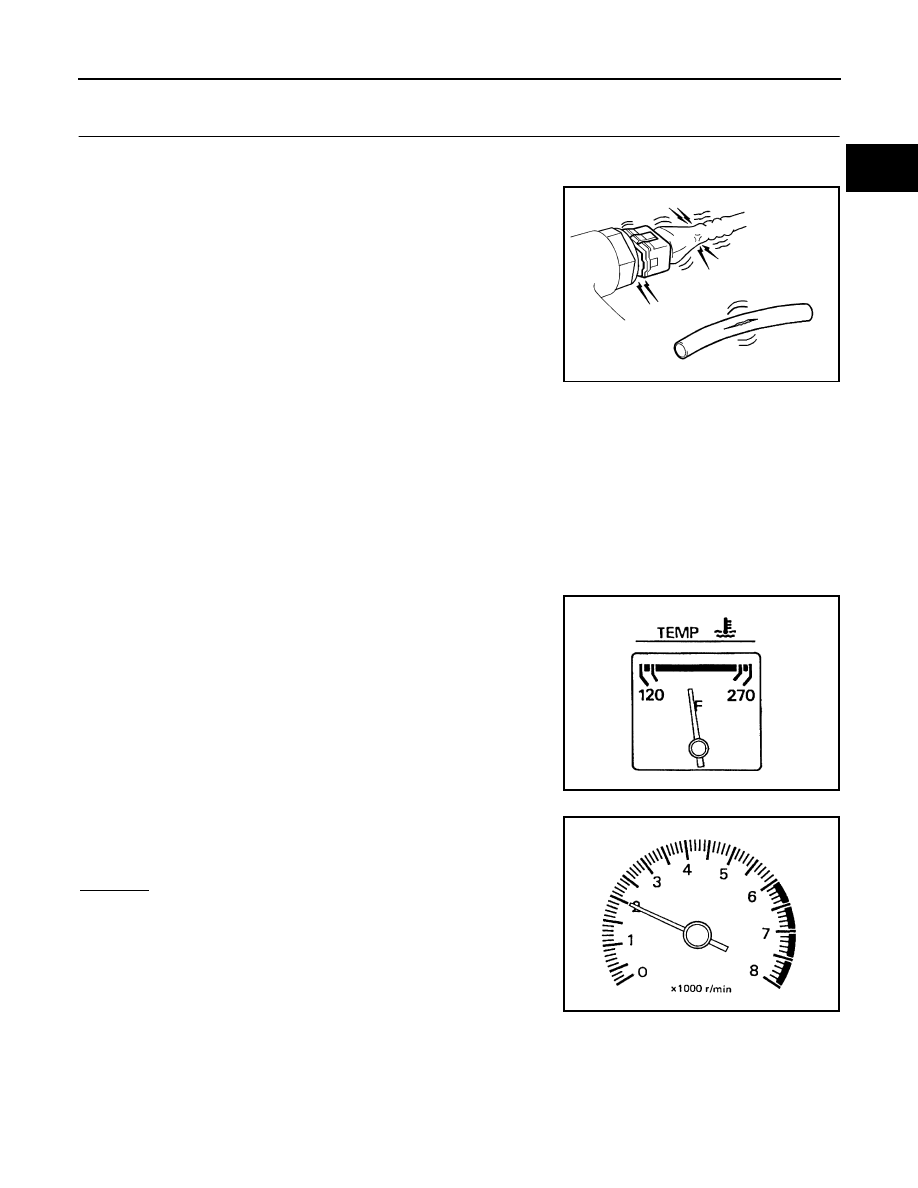
Vacuum hoses for splits, kinks and improper connections

Hoses and ducts for leaks

Air cleaner clogging

Gasket

3.

Confirm that electrical or mechanical loads are not applied.

Headlamp switch is OFF.

Air conditioner switch is OFF.

Rear window defogger switch is OFF.

Steering wheel is in the straight-ahead position, etc.

4.

Visually check the following:

Air cleaner clogging

Hoses and ducts for leaks

Electrical connectors

Gasket

Throttle valve and throttle position sensor operation

5.

Start engine and warm it up until engine coolant temperature indicator points to the middle of gauge.
Ensure engine stays below 1,000 rpm.

6.

Open engine hood and run engine at about 2,000 rpm for about
2 minutes under no-load.

7.

Make sure that no DTC is displayed with CONSULT-II or GST.

OK or NG

OK

>> GO TO 2.

NG

>> 1. Repair or replace components as necessary.

2. GO TO 2.

SEF983U

SEF976U

SEF977U

EC-1208

[VG33ER]

BASIC SERVICE PROCEDURE

2. 

CHECK IGNITION TIMING

1.

Run engine at about 2,000 rpm for about 2 minutes under no-load.

2.

Rev engine (2,000 to 3,000 rpm) two or three times under no-
load, then run engine at idle speed.

3.

Stop engine and disconnect throttle position sensor harness
connector.

4.

Start and rev engine (2,000 to 3,000 rpm) two or three times
under no-load, then run at idle speed.

5.

Check ignition timing with a timing light.

OK or NG

OK

>> GO TO 4.

NG

>> GO TO 3.

3. 

ADJUST IGNITION TIMING

1.

Adjust ignition timing by turning distributor after loosening securing bolts.

2.

Stop engine and connect throttle position sensor harness con-
nector to throttle position sensor.

>> GO TO 2.

SEF978U

BBIA0424E

M/T: 10

°±5° BTDC (in Neutral position)

A/T: 10

°±5° BTDC (in P or N position)

SEF927Z

BBIA0425E

BASIC SERVICE PROCEDURE

EC-1209

[VG33ER]

C

D

E

F

G

H

I

J

K

L

M

A

EC

4. 

CHECK BASE IDLE SPEED

 With CONSULT-II

1.

Read idle speed in “DATA MONITOR” mode with CONSULT-II.

 Without CONSULT-II

1.

Check idle speed.

OK or NG

OK

>> GO TO 6.

NG

>> GO TO 5.

5. 

ADJUST BASE IDLE SPEED

1.

Rev engine (2,000 to 3,000 rpm) 2 or 3 times under no load then run engine at idle speed.

2.

Adjust idle speed by turning idle speed adjusting screw.

>> GO TO 6.

6. 

CHECK TARGET IDLE SPEED

 With CONSULT-II

1.

Stop engine and connect throttle position sensor harness connector.

2.

Start and rev engine (2,000 to 3,000 rpm) 2 or 3 times under no-load then run at idle speed.

3.

Read idle speed in “DATA MONITOR” mode with CONSULT-II.

 Without CONSULT-II

1.

Stop engine and connect throttle position sensor harness con-
nector.

2.

Start and rev engine (2,000 to 3,000 rpm) 2 or 3 times under no-
load then run at idle speed.

3.

Check idle speed.

OK or NG

OK (With CONSULT-II)>>GO TO 8.
OK (Without CONSULT-II)>>GO TO 9.
NG

>> GO TO 7.

M/T: 700

±50 rpm (in Neutral position)

A/T: 700

±50 rpm (in P or N position)

M/T: 700

±50 rpm (in Neutral position)

A/T: 700

±50 rpm (in P or N position)

SEF058Y

M/T: 700

±50 rpm (in Neutral position)

A/T: 700

±50 rpm (in P or N position)

LEC513

M/T: 750

±50 rpm (in Neutral position)

A/T: 750

±50 rpm (in P or N position)

M/T: 750

±50 rpm (in Neutral position)

A/T: 750

±50 rpm (in P or N position)

SEF058Y

EC-1210

[VG33ER]

BASIC SERVICE PROCEDURE

7. 

DETECT MALFUNCTIONING PART

Check the following.

1.

Check IACV-AAC valve and replace if necessary. Refer to 

EC-1573

 .

2.

Check IACV-AAC valve harness and repair if necessary. Refer to 

EC-1573

 .

3.

Check ECM function by substituting another known-good ECM.
(ECM may be the cause of an incident, but this is a rare case.)

With CONSULT-II>>GO TO 8.
Without CONSULT-II>>GO TO 9.

8. 

CHECK HEATED OXYGEN SENSOR 1 (BANK 2) SIGNAL

 With CONSULT-II

1.

Run engine at about 2,000 rpm for about 2 minutes under no load.

2.

See “HO2S1 MNTR (B2)” in “DATA MONITOR” mode.

3.

Running engine at 2,000 rpm under no load (engine is warmed
up to normal operating temperature.), check that the monitor
fluctuates between “LEAN” and “RICH” more than 5 times dur-
ing 10 seconds.

OK or NG

OK

>> GO TO 12.

NG (Monitor does not fluctuate.)>>GO TO 17.
NG (Monitor fluctuates less than 5 times.)>>GO TO 10.

9. 

CHECK HEATED OXYGEN SENSOR 1 (BANK 2) SIGNAL

 Without CONSULT-II

1.

Run engine at about 2,000 rpm for about 2 minutes under no
load.

2.

Set voltmeter probe between ECM terminal 51 and ground.

3.

Make sure that the voltage fluctuates between 0 - 0.3V and 0.6 -
1.0V more than 5 times during 10 seconds at 2,000 rpm.
1 time: 0 - 0.3V 

 0.6 - 1.0V  0 - 0.3V

2 times: 0 - 0.3V 

 0.6 - 1.0V  0 - 0.3V  0.6 - 1.0V  0 -

0.3V

OK or NG

OK

>> GO TO 12.

NG (Voltage does not fluctuate.)>>GO TO 17.
NG (Voltage fluctuates less than 5 times.)>>GO TO 10.

1 time: RICH 

 LEAN  RICH

2 times: RICH 

 LEAN  RICH  LEAN  RICH

PBIB0120E

PBIB2157E


Content   ..  524  525  526  527   ..