Nissan Frontier D22. Manual - part 524
ENGINE CONTROL SYSTEM
EC-1199
[VG33ER]
C
D
E
F
G
H
I
J
K
L
M
A
EC
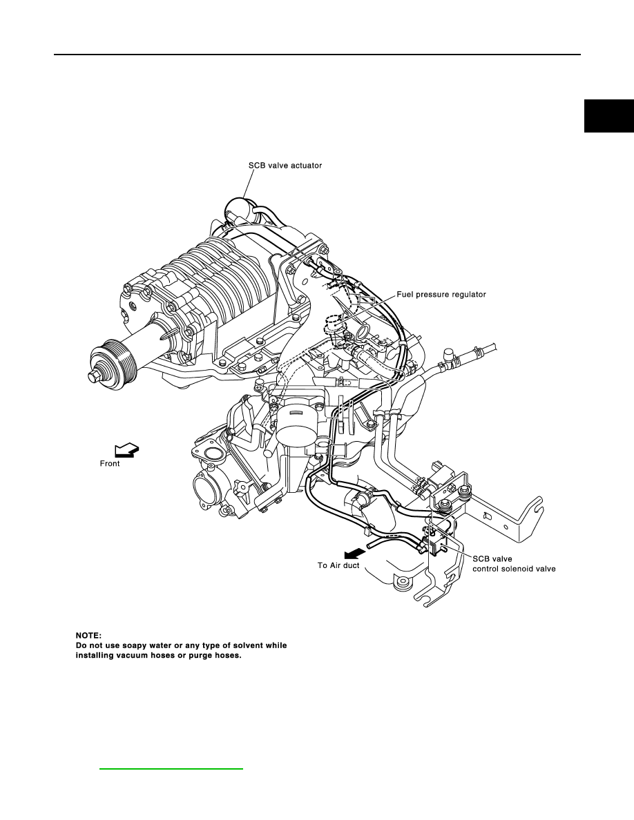
Vacuum Hose Drawing
UBS00DRO
Refer to
for Vacuum Control System.
PBIB1342E
|
|
|
ENGINE CONTROL SYSTEM EC-1199 [VG33ER] C D E F G H I J K L M A EC Vacuum Hose Drawing UBS00DRO Refer to for Vacuum Control System. PBIB1342E |