Nissan Frontier D22. Manual - part 439
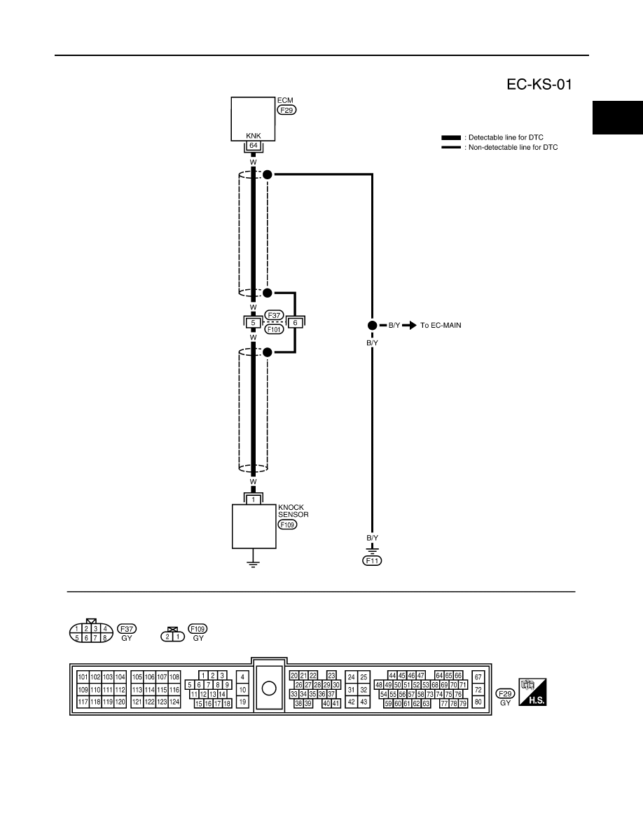
DTC P0327, P0328 KS
EC-859
[VG33E]
C
D
E
F
G
H
I
J
K
L
M
A
EC
Wiring Diagram
UBS00DJK
BBWA0480E
|
|
|
DTC P0327, P0328 KS EC-859 [VG33E] C D E F G H I J K L M A EC Wiring Diagram UBS00DJK BBWA0480E |