Nissan Frontier D22. Manual - part 197


  Index      Nissan     Nissan Frontier D22 Pickup (1998-2004 year) - Service and Repair Manual


Search            


Content   ..  195  196  197  198   ..


Nissan Frontier D22. Manual - part 197


TROUBLE DIAGNOSIS

BRC-119

[VDC/TCS/ABS]

C

D

E

G

H

I

J

K

L

M

A

B

BRC

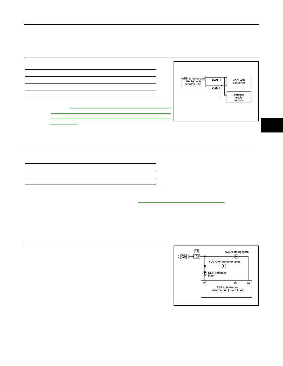
Inspection 23 CAN CIRCUIT 1 - CAN Communication System Failure

EFS003IU

DTC C1174

1. 

INSPECTION START

Check self-diagnosis results.

Do self-diagnosis results indicate anything other than the above?

YES

>> Perform repair or replacement for the item indicated.

NO

>> Refer to 

BRC-106, "Inspection 12 CAN Communications

Lines, ABS Actuator and Electric Unit (Control Unit),
Steering Angle Sensor System and CAN-LAN Converter
ECU (CLC)"

 .

Inspection 24 CAN-LAN Converter (CLC) Control Unit

EFS003IV

1. 

INSPECTION START

Check self-diagnosis results.

Do self-diagnosis results indicate anything other than the above?

YES

>> Perform repair or replacement for the item indicated.

NO

>> Replace CAN-LAN converter. Refer to 

BRC-131, "CAN-LAN Converter (CLC)"

 . Perform self-

diagnosis again.

Inspection 25 ABS Warning Lamp Does Not Come On When Ignition Switch Is 
Turned On

EFS003IW

1. 

INSPECTION START

Warning lamp circuit inspection.

>> GO TO 2.

Self-diagnosis results

CONSULT-II display items

CAN CIRCUIT 1

LFIA0170E

Self-diagnosis results

CONSULT-II display items

CLC CONTROL UNIT

LFIA0162E

BRC-120

[VDC/TCS/ABS]

TROUBLE DIAGNOSIS

2. 

CHECK FUSE

Check 10A fuse [No. 11 located in the fuse block (J/B)]. For fuse layout, refer to 

PG-9, "POWER SUPPLY

ROUTING"

 .

OK or NG?

OK

>> GO TO 3.

NG

>> Replace fuse.

3. 

CHECK POWER SUPPLY CIRCUIT

1.

Install 10A fuse.

2.

Disconnect ABS actuator and electric unit (control unit) connector.

3.

Turn ignition switch ON.

4.

Check voltage between ABS actuator and electric unit (control
unit) connector E39 terminal 44 (L/W) and ground.

OK or NG?

OK

>> GO TO 5.

NG

>> GO TO 4.

4. 

CHECK INDICATOR BULB

Check indicator lamp bulb.

OK or NG?

OK

>> Repair harness or connectors between fuse and ABS actuator and electric unit (control unit) ter-

minal 44 (including combination meter).

NG

>> Replace combination meter.

5. 

CHECK CIRCUIT

1.

Turn ignition switch OFF.

2.

Disconnect ABS actuator and electric unit (control unit) and combination meter connectors.

3.

Check continuity between ABS actuator and electric unit (control
unit) connector E39 terminal 44 (L/W) and combination meter
connector M38 terminal 24 (L/W).

Battery voltage should exist.

LFIA0184E

Continuity should exist.

LFIA0185E

TROUBLE DIAGNOSIS

BRC-121

[VDC/TCS/ABS]

C

D

E

G

H

I

J

K

L

M

A

B

BRC

OK or NG?

OK

>> Reconnect connectors and perform self-diagnosis. Repair or replace.

NG

>>

Check harness connectors E39, M38

Harness for open or short between ABS actuator and electric unit (control unit) and combina-
tion meter

Inspection 26 When "DECEL G-SENSOR" Appears on Self-Diagnosis Results 
Display

EFS003IX

DTC 1113

1. 

CHECKING SELF-DIAGNOSIS RESULTS (1)

Check self-diagnosis results.

Does anything besides "DECEL G-SENSOR" appear on self-diagnosis results display?

YES

>> Inspect and repair the indicated items. Then perform self-diagnosis again.

NO

>> Perform calibration of decel G-sensor. Refer to 

BRC-55, "Calibration of Decel G Sensor"

 .

2. 

CHECKING SELF-DIAGNOSIS RESULTS (2)

Turn ignition switch OFF and ON to erase self-diagnosis results and perform VDC/TCS/ABS self-diagnosis.

Does anything appear on self-diagnosis results display?

YES

>> Replace decel G-sensor. Refer to 

BRC-131, "Yaw Rate/Side/Decel G Sensor"

 . Then perform cal-

ibration of decel G-sensor and self-diagnosis again. Refer to 

BRC-55, "Calibration of Decel G

Sensor"

 .

NO

>> Inspection is completed.

Inspecting Components

EFS003IY

VDC OFF SWITCH

Remove VDC OFF switch. Check continuity between terminals
1 and 2 as follows.

Self-diagnosis results

CONSULT-II display items

DECEL G-SENSOR

Switch condition:

Continuity

Pressed

: Yes

Released

: No

LFIA0154E

BRC-122

[VDC/TCS/ABS]

TROUBLE DIAGNOSIS

Symptom 1 ABS Works Frequently

EFS003IZ

Inspection Procedure

1. 

STARTING INSPECTION

Inspect wheel sensor system.

Sensor mounting inspection

Sensor pick-up inspection for iron chips

Sensor rotor inspection (e.g. Number of teeth, damaged teeth)

Sensor connector engagement inspection

Is inspection result OK?

OK

>> GO TO 2.

NG

>> Repair wheel sensor and rotor system.

2. 

CHECKING FOR LOOSENESS

Check for looseness of front axle.
Is inspection result OK?

OK

>> GO TO 

BRC-122, "Symptom 2 Unexpected Pedal Reaction"

 .

NG

>> Axle inspection and repair.

Symptom 2 Unexpected Pedal Reaction

EFS003J0

Inspection Procedure

1. 

BRAKE PEDAL STROKE INSPECTION

Check brake pedal stroke.

Is stroke excessively long?

YES

>> Check bleeding and brake system.

NO

>> GO TO 2.

2. 

CHECKING PEDAL FORCE

Check that brake is effective with pedal depressed.
Is pedal heavy, but effective?

YES

>> Normal.

NO

>> GO TO 3.

3. 

CONNECTOR AND PERFORMANCE INSPECTION

Disconnect ABS actuator and electric unit (control unit) connector to deactivate ABS function. Check that
brake is effective.
Is brake effective?

YES

>> GO TO 4.

NO

>> Brake line inspection.

4. 

CHECKING ABS WARNING LAMP INDICATION

Check that ABS warning lamp illuminates.

Is inspection result OK?

OK

>> Perform self-diagnosis.

NG

>> GO TO 5.


Content   ..  195  196  197  198   ..