Nissan Frontier D22. Manual - part 195
TROUBLE DIAGNOSIS
BRC-111
[VDC/TCS/ABS]
C
D
E
G
H
I
J
K
L
M
A
B
BRC
4.
CHECK ABS ACTUATOR AND ELECTRIC UNIT (CONTROL UNIT) SELF-DIAGNOSIS (2)
Does any other self-diagnostic item appear on display?
YES
>> Repair or replace.
NO
>> GO TO 5.
5.
CHECK VOLTAGE
1.
Check if battery voltage is too low (less than 9V) or battery terminals are loose.
OK or NG?
OK
>> GO TO 6.
NG
>> Faulty battery.
6.
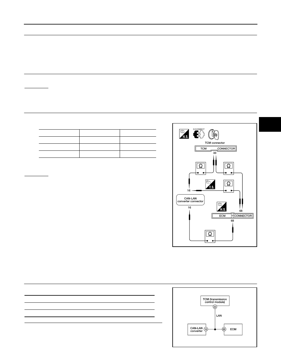
CHECK LAN CIRCUIT
1.
Disconnect CAN-LAN converter (CLC), TCM and ECM connectors.
2.
Check continuity between connector terminals.
OK or NG?
OK
>> Connect connectors and repeat self-diagnosis. Repair
or replace.
NG
>>
●
Check the following
–
Harness connectors M147, M78, F29
–
Harness for open or short between ABS actuator and
electric unit (control unit) and ECM
–
Harness for open or short between ABS actuator and
electric unit (control unit) and TCM
–
Harness for open or short between ECM and TCM
●
If NG, repair harness or connectors.
Inspection 16 LAN SIGNAL 2 - LAN Communication Start Procedure Incomplete
EFS003IN
DTC C1172
1.
INSPECTION START
Check self-diagnosis results.
Do self-diagnosis results indicate anything other than the above?
YES
>> Perform repair or replacement for the item indicated.
NO
>> GO TO 2.
CLC
ECM
TCM
16 (W/G)
68 (W/G)
—
16 (W/G)
—
33 (W/G)
—
68 (W/G)
33 (W/G)
Continuity should exist.
LFIA0158E
Self-diagnosis results
CONSULT-II display items
LAN SIGNAL 2
LFIA0157E