Nissan Frontier D22. Manual - part 196


  Index      Nissan     Nissan Frontier D22 Pickup (1998-2004 year) - Service and Repair Manual


Search            


Content   ..  194  195  196  197   ..


Nissan Frontier D22. Manual - part 196


TROUBLE DIAGNOSIS

BRC-115

[VDC/TCS/ABS]

C

D

E

G

H

I

J

K

L

M

A

B

BRC

OK or NG?

OK

>> Reconnect connectors and perform self-diagnosis. Repair or replace.

NG

>>

Check harness connectors E39, M38

Harness for open or short between ABS actuator and electric unit (control unit) and combina-
tion meter

Inspection 20 VDC OFF Indicator Lamp Does Not Come On When Ignition 
Switch Is Turned On

EFS003IR

1. 

INSPECTION START

Indicator lamp circuit inspection.

>> GO TO 2.

2. 

CHECK FUSE

Check 10A fuse [No. 11 located in the fuse block (J/B)]. For fuse layout, refer to 

PG-9, "POWER SUPPLY

ROUTING"

 .

OK or NG?

OK

>> GO TO 3.

NG

>> Replace fuse.

3. 

CHECK POWER SUPPLY CIRCUIT

1.

Install 10A fuse.

2.

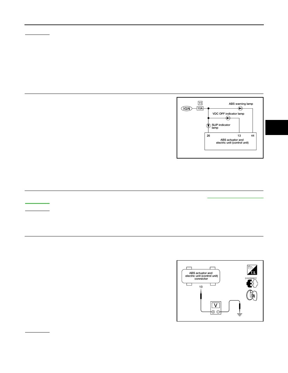
Disconnect ABS actuator and electric unit (control unit) connector.

3.

Turn ignition switch ON.

4.

Check voltage between ABS actuator and electric unit (control
unit) connector E39 terminal 13 (L/B) and ground.

OK or NG?

OK

>> GO TO 5.

NG

>> GO TO 4.

LFIA0162E

Battery voltage should exist.

LFIA0163E

BRC-116

[VDC/TCS/ABS]

TROUBLE DIAGNOSIS

4. 

CHECK INDICATOR BULB

Check indicator lamp bulb.

OK or NG?

OK

>> Repair harness or connectors between fuse and ABS actuator and electric unit (control unit) ter-

minal 13 (including combination meter).

NG

>> Replace combination meter.

5. 

CHECK CIRCUIT

1.

Turn ignition switch OFF.

2.

Disconnect ABS actuator and electric unit (control unit) and combination meter connectors.

3.

Check continuity between ABS actuator and electric unit (control
unit) connector E39 terminal 13 (L/B) and combination meter
connector M38 terminal 4 (L/B).

OK or NG?

OK

>> Reconnect connectors and perform self-diagnosis. Repair or replace.

NG

>>

Check harness connectors E39, M38

Harness for open or short between ABS actuator and electric unit (control unit) and combina-
tion meter

Inspection 21 VDC OFF Switch Is Inoperative

EFS003IS

1. 

INSPECTION START

Inspect VDC OFF switch circuit.

>> GO TO 2.

2. 

CHECK VDC OFF SWITCH

Refer to 

BRC-121, "VDC OFF SWITCH"

 .

OK or NG?

OK

>> GO TO 3.

NG

>> Replace VDC OFF switch.

Continuity should exist.

LFIA0172E

LFIA0164E

TROUBLE DIAGNOSIS

BRC-117

[VDC/TCS/ABS]

C

D

E

G

H

I

J

K

L

M

A

B

BRC

3. 

CHECK VDC OFF SWITCH CIRCUIT FOR OPEN

1.

Disconnect ABS actuator and electric unit (control unit) connector and VDC OFF switch connector.

2.

Check continuity between ABS actuator and electric unit (control
unit) connector E39 terminal 40 (PU/W) and VDC OFF switch
connector M146 terminal 2 (PU/W).

OK or NG?

OK

>> GO TO 4.

NG

>> Repair harness or connectors.

4. 

CHECK VDC OFF SWITCH CIRCUIT FOR SHORT

1.

Check continuity between VDC OFF switch connector M146 ter-
minal 2 (PU/W) and ground.

OK or NG?

OK

>> GO TO 5.

NG

>> Repair harness or connectors.

5. 

CHECK GROUND CIRCUIT

1.

Check continuity between VDC OFF switch connector M146 ter-
minal 1 (G/R) and ground.

OK or NG?

OK

>> Reconnect connectors and perform self-diagnosis. Repair or replace.

NG

>> Repair harness or connectors.

Inspection 22 CAN-LAN Converter Power Supply Circuit

EFS003IT

DTC C1177

Continuity should exist.

LFIA0165E

Continuity should not exist.

LFIA0166E

Continuity should exist.

LFIA0167E

BRC-118

[VDC/TCS/ABS]

TROUBLE DIAGNOSIS

1. 

SELF-DIAGNOSIS RESULT CHECK 1

Check self-diagnosis results.

Do self-diagnosis results indicate anything other than the above?

YES

>> Perform repair or replacement for the item indicated.

NO

>> GO TO 2.

2. 

SELF-DIAGNOSIS RESULT CHECK 2

1.

Disconnect the CAN-LAN converter (CLC) connector. Securely connect it again.

2.

Perform self-diagnosis.

Does "CLC BATTERY VOLTAGE [ABNORMAL]" appear on display?

YES

>> GO TO 3.

NO

>> Repair or replace the connector.

3. 

CHECK CLC POWER SUPPLY CIRCUIT

1.

Disconnect CLC connector.

2.

Turn ignition switch ON.

3.

Check voltage between CLC connector M147 terminal 1 (W/B)
and ground.

OK or NG?

OK

>> GO TO 4.

NG

>> Repair harness or connectors.

4. 

CHECK CLC GROUND CIRCUIT

1.

Check continuity between CLC connector M147 terminal 10 (B)
and ground.

OK or NG?

OK

>> Reconnect connectors and perform self-diagnosis. Repair or replace.

NG

>> Repair harness or connectors.

Self-diagnosis results

CONSULT-II display items

CLC BATTERY VOLTAGE [ABNORMAL]

Battery voltage should exist.

LFIA0168E

Continuity should exist.

LFIA0169E


Content   ..  194  195  196  197   ..