Nissan Frontier D22. Manual - part 188
 

  Index      Nissan     Nissan Frontier D22 Pickup (1998-2004 year) - Service and Repair Manual


Search            


Content   ..  186  187  188  189   ..


Nissan Frontier D22. Manual - part 188


TROUBLE DIAGNOSIS

BRC-83

[VDC/TCS/ABS]

C

D

E

G

H

I

J

K

L

M

A

B

BRC

Note 1. If wheel sensor 2 for each wheel is indicated, check ABS actuator and electric unit (control unit) power
supply voltage in addition to wheel sensor circuit check.
Note 2. If multiple malfunctions are detected including CAN communication line [U1000], perform diagnosis for
CAN communication line first.
Note 3: "ACTUATOR RLY" on the CONSULT-II self-diagnosis results indicates the malfunction of the actuator
motor relay or circuit.

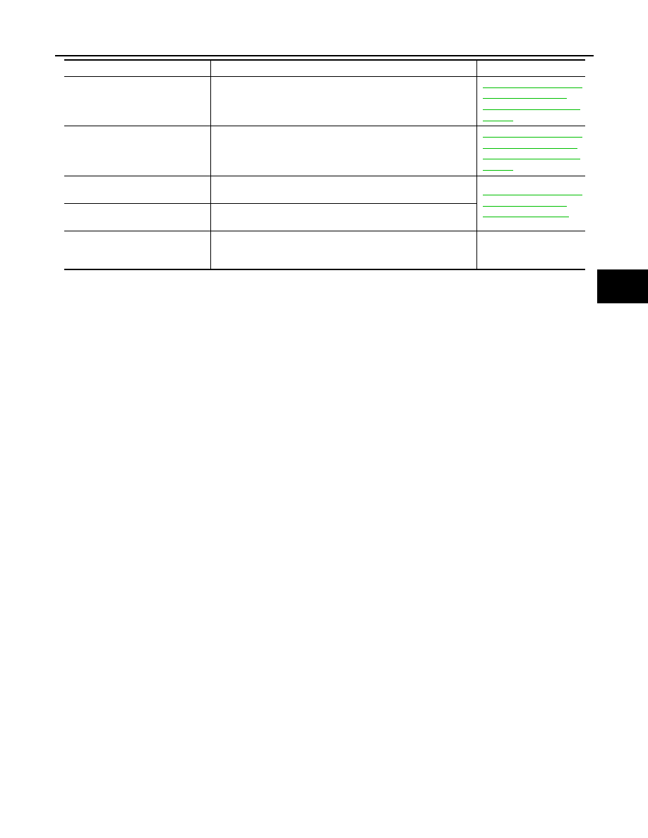
ENGINE CHECK SIG
[C1171]

ECM judges the communication between VDC control unit or 
CLC and ECM is abnormal.

BRC-112, "Inspection 17 
LAN COMM 1 - LAN 
Communication System 
Failure"

CAN COMM 1
[C1174]

CLC judges the CAN communication line between VDC control 
unit and CLC is open or shorted.

BRC-119, "Inspection 23 
CAN CIRCUIT 1 - CAN 
Communication System 
Failure"

CLC CONTROL UNIT
[C1175]

Function of calculation in CLC has failed.

BRC-117, "Inspection 22 
CAN-LAN Converter 
Power Supply Circuit"

CLC BATTERY VOLT
[C1177]

Power source voltage supplied to CLC is abnormally low.

VARIANT CODING
[C1170]

V coding is not functioning.

The ABS actuator and 
electric unit (control unit) 
and circuit

Self-diagnostic item

Malfunction detecting condition

Check system

BRC-84

[VDC/TCS/ABS]

TROUBLE DIAGNOSIS

DATA MONITOR

For details of data monitor function, refer to “CONSULT-II Instruction Manual”.

Operation Procedure

1.

Turn ignition switch OFF.

2.

Connect CONSULT-II to data link connector.

CAUTION:

If CONSULT-II is used with no connection of CONSULT-II
CONVERTER, malfunctions might be detected in self-diag-
nosis depending on control unit which carry out CAN com-
munication.

3.

Turn ignition switch ON.

4.

Touch “START” on display.

5.

Touch “ABS” on display.

6.

Touch “DATA MONITOR”.

7.

Return to monitor item selection screen and touch any of “ECU
INPUT SIGNALS”,  “MAIN SIGNALS”, "CAN DIAG SUPPORT
MNTR" or "SELECTION FROM MENU". Refer to 

BRC-85, "Dis-

play Item List"

 .

8.

Touch “START”.

9.

Screen of data monitor is displayed.

LEC104A

PBR385C

WFIA0043E

LFIA0141E

TROUBLE DIAGNOSIS

BRC-85

[VDC/TCS/ABS]

C

D

E

G

H

I

J

K

L

M

A

B

BRC

Display Item List

Item

(Unit)

Data monitor item selection

Remarks

ECU INPUT 

SIGNALS

MAIN

SIGNALS

SELECTION

FROM 
MENU

CAN DIAG
SUPPORT

MNTR

GEAR

×

×

×

Gear position judged by TCM 
signal is displayed.

FR RH SENSOR 
 (km/h, MPH)

×

×

×

Wheel speed calculated by 
front RH wheel sensor signal 
is displayed.

FR LH SENSOR 
 (km/h, MPH)

×

×

×

Wheel speed calculated by 
front LH wheel sensor signal 
is displayed.

RR RH SENSOR
 (km/h, MPH)

×

×

×

Wheel speed calculated by 
rear RH wheel sensor signal 
is displayed.

RR LH SENSOR 
 (km/h, MPH)

×

×

×

Wheel speed calculated by 
rear LH wheel sensor signal is 
displayed.

BATTERY VOLT
(V)

×

×

×

Voltage supplied to ABS actu-
ator and electric unit (control 
unit) is displayed.

SLCT LVR POSI

×

×

×

Shift position judged by PNP, 
reverse switch signal.

ACCEL POS SIG
(%)

×

×

Throttle valve open/close sta-
tus judged by ECM signal is 
displayed.

ENGINE SPEED
(rpm)

×

×

×

Engine speed judged by ECM 
signal is displayed.

STR ANGLE SIG
(deg)

×

×

Steering angle detected by 
steering angle sensor is dis-
played.

YAW RATE SEN
(d/s)

×

×

×

Yaw rate detected by yaw rate 
sensor is displayed.

DECEL G SEN
(G)

×

×

×

Longintudinal acceleration 
detected by decel G sensor is 
displayed.

SIDE G-SENSOR

(m/s

2

 )

×

×

Transverse acceleration 
detected by side G-sensor is 
displayed.

PRESS SENSOR
(bar)

×

×

Brake fluid pressure detected 
by pressure sensor is dis-
played.

STOP LAMP SW
(ON/OFF)

×

×

×

Stop lamp switch (ON/OFF) 
status is displayed.

OFF  SW
(ON/OFF)

×

×

×

VDC OFF switch (ON/OFF) 
status is displayed.

ABS WARN LAMP
(ON/OFF)

×

×

ABS warning lamp (ON/OFF) 
status is displayed.

SLIP LAMP
(ON/OFF)

×

×

SLIP indicator lamp (ON/
OFF) status is displayed.

FR LH IN SOL
(ON/OFF)

×

×

Front LH IN ABS solenoid 
(ON/OFF) status is displayed.

FR LH OUT SOL
(ON/OFF)

×

×

Front LH OUT ABS solenoid 
(ON/OFF) status is displayed.

BRC-86

[VDC/TCS/ABS]

TROUBLE DIAGNOSIS

RR RH IN SOL
(ON/OFF)

×

×

Rear RH IN ABS solenoid 
(ON/OFF) status is displayed.

RR RH OUT SOL
(ON/OFF)

×

×

Rear RH OUT ABS solenoid 
(ON/OFF) status is displayed.

FR RH IN SOL
(ON/OFF)

×

×

Front RH IN ABS solenoid 
(ON/OFF) status is displayed.

FR RH OUT SOL
(ON/OFF)

×

×

Front RH OUT ABS solenoid 
(ON/OFF) status is displayed.

RR LH IN SOL
(ON/OFF)

×

×

Rear LH IN ABS solenoid 
(ON/OFF) status is displayed.

RR LH OUT SOL
(ON/OFF)

×

×

Rear LH OUT ABS solenoid 
(ON/OFF) status is displayed.

OFF LAMP
(ON/OFF)

×

×

OFF Lamp (ON/OFF) status 
is displayed.

MOTOR RELAY
(ON/OFF)

×

×

ABS motor relay signal (ON/
OFF) status is displayed.

ACTUATOR RLY
(ON/OFF)

×

×

ABS actuator relay signal 
(ON/OFF) status is displayed.

CV1
(ON/OFF)

×

Front side switch-over sole-
noid valve (cut valve 1) (ON/
OFF) status is displayed.

CV2
(ON/OFF)

×

Rear side switch-over sole-
noid valve (cut valve 2) (ON/
OFF) status is displayed.

SV1
(ON/OFF)

×

Front side switch-over sole-
noid valve (suction valve 1) 
(ON/OFF) status is displayed.

SV2
(ON/OFF)

×

Rear side switch-over sole-
noid valve (suction valve 2) 
(ON/OFF) status is displayed.

VDC FAIL SIG
(ON/OFF)

×

VDC fail signal (ON/OFF) sta-
tus is displayed.

TCS FAIL SIG
(ON/OFF)

×

TCS fail signal (ON/OFF) sta-
tus is displayed.

ABS FAIL SIG
(ON/OFF)

×

ABS fail signal (ON/OFF) sta-
tus is displayed.

EBD FAIL SIG
(ON/OFF)

×

EBD fail signal (ON/OFF) sta-
tus is displayed.

FLUID LEV SW
(ON/OFF)

×

×

Brake fluid level switch (ON/
OFF) status is displayed.

EBD SIGNAL
(ON/OFF)

×

EBD operation (ON/OFF) sta-
tus is displayed.

ABS SIGNAL
(ON/OFF)

×

ABS operation (ON/OFF) sta-
tus is displayed.

TCS SIGNAL
(ON/OFF)

×

TCS operation (ON/OFF) sta-
tus is displayed.

VDC SIGNAL
(ON/OFF)

×

VDC operation (ON/OFF) sta-
tus is displayed.

CAN COMM
(OK/NG)

×

CAN communication signal 
(OK/NG) status is displayed.

Item

(Unit)

Data monitor item selection

Remarks

ECU INPUT 

SIGNALS

MAIN

SIGNALS

SELECTION

FROM 
MENU

CAN DIAG
SUPPORT

MNTR


Content   ..  186  187  188  189   ..