Nissan Frontier D22. Manual - part 187


  Index      Nissan     Nissan Frontier D22 Pickup (1998-2004 year) - Service and Repair Manual


Search            


Content   ..  185  186  187  188   ..


Nissan Frontier D22. Manual - part 187


TROUBLE DIAGNOSIS

BRC-79

[VDC/TCS/ABS]

C

D

E

G

H

I

J

K

L

M

A

B

BRC

CONSULT-II BASIC OPERATION PROCEDURE

1.

Turn ignition switch OFF.

2.

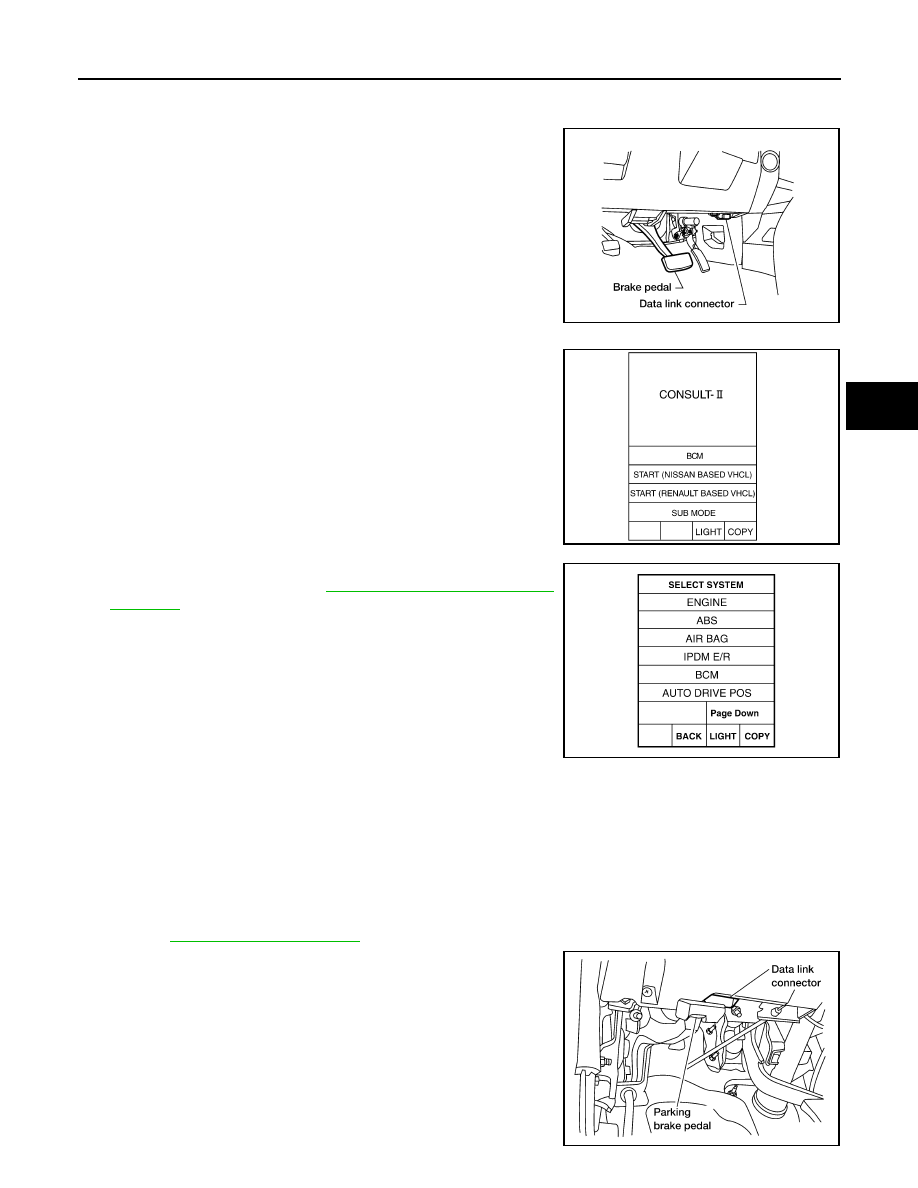
Connect CONSULT-II and CONSULT-II CONVERTER to the
data link connector.

CAUTION:

If CONSULT-II is used with no connection of CONSULT-II
CONVERTER, malfunctions might be detected in self-diag-
nosis depending on control unit which carry out CAN com-
munication.

3.

Turn ignition switch ON.

4.

Touch “START (NISSAN BASED VHCL)”. 

5.

Touch “ABS” in the “Diagnosis System Selection” screen.
If “ABS” is not indicated, go to 

GI-35, "CONSULT-II CHECKING

SYSTEM"

 .

6.

Select the required diagnostic location from the “Diagnosis Mode Selection” screen.
For further information, see the CONSULT-II Operation Manual.

SELF-DIAGNOSIS
Description

If a malfunction is detected in system, ABS warning lamp, VDC OFF indicator lamp, and SLIP indicator lamp
in combination meter turn ON. In this case, perform self-diagnosis as follows:

Operation Procedure

1.

Perfor

BRC-92, "Basic Inspection"

   using information from customer.

2.

After ignition switch is turned OFF, connect CONSULT-II to data
link connector.

CAUTION:

If CONSULT-II is used with no connection of CONSULT-II
CONVERTER, malfunctions might be detected in self-diag-
nosis depending on control unit which carry out CAN com-
munication.

3.

Start engine and drive at approximately 30 km/h (19 MPH) for
approximately 1 minute.

BBIA0369E

WKIA1606E

LKIA0339E

LEC104A

BRC-80

[VDC/TCS/ABS]

TROUBLE DIAGNOSIS

4.

After stopping vehicle, with engine still idling, touch “START”,  “ABS”, and “SELF-DIAG RESULTS” on
CONSULT-II screen in this order.

CAUTION:

Just after starting engine, or turning ignition switch ON, “ABS” may not be displayed on system
selection screen even if “START” is touched. In this case, start self-diagnosis again from step 2. If
it cannot be shown after several attempts, ABS actuator and electric unit (control unit) may have
malfunctioned. Replace ABS actuator and electric unit (control unit). Refer to 

BRC-130, "ABS

Actuator and Electric Unit"

 .

5.

Self-diagnosis result is displayed. (If necessary, touch “PRINT” to print self-diagnosis result.)

When  “NO FAILURE” is shown, check ABS warning lamp, VDC OFF indicator lamp, SLIP indicator
lamp. Refer to 

BRC-90, "For Fast and Accurate Diagnosis"

 . 

CONSULT-II self-diagnosis results are displayed without regard to occurrence timing. In some cases
later ones (timing value is small) appear on next screen.

6.

Go to appropriate “Inspection” chart according to “Display Item List”, and repair or replace as necessary.

7.

Start engine and drive at approximately 30 km/h (19 MPH) for approximately 1 minute.

CAUTION:

Check again to make sure that there is no malfunction on other parts.

8.

Turn ignition switch OFF to prepare for erasing memory.

9.

Start engine and touch “START”,  “ABS”,  “SELF-DIAGNOSIS RESULTS”, and “ERASE MEMORY” on
CONSULT-II screen in this order to erase memory.

CAUTION:

If memory cannot be erased, return to step 6.

10. Drive vehicle at approximately 30 km/h (19 MPH) and check that ABS warning lamp, VDC OFF indicator

lamp, and SLIP indicator lamp stay off.

Self-Diagnostic Results Mode

Self-diagnostic item

Malfunction detecting condition

Check system

FR LH SENSOR- 1
[C1104]

Circuit of front LH wheel sensor is open, shorted or sensor power 
voltage is unusual

BRC-94, "Inspection 1 
Wheel Sensor System"


(Note 1)

RR RH SENSOR- 1
[C1101

Circuit of rear RH wheel sensor is open, shorted or sensor power 
voltage is unusual

FR RH SENSOR- 1
[C1103]

Circuit of front RH wheel sensor is open, shorted or sensor power 
voltage is unusual

RR LH SENSOR- 1
[C1102]

Circuit of rear LH wheel sensor is open, shorted or sensor power 
voltage is unusual

FR LH SENSOR- 2
[C1108]

ABS actuator and electric unit (control unit) cannot identify sen-
sor pulses, because of large gap between wheel sensor and sen-
sor rotor.

RR RH SENSOR- 2
[C1105]

ABS actuator and electric unit (control unit) cannot identify sen-
sor pulses, because of large gap between wheel sensor and sen-
sor rotor.

FR RH SENSOR- 2
[C1107]

ABS actuator and electric unit (control unit) cannot identify sen-
sor pulses, because of large gap between wheel sensor and sen-
sor rotor.

RR LH SENSOR- 2
[C1106]

ABS actuator and electric unit (control unit) cannot identify sen-
sor pulses, because of large gap between wheel sensor and sen-
sor rotor.

STOP LAMP SW
[C1116]

Stop lamp switch circuit is open.

BRC-102, "Inspection 8 
Stop Lamp Switch and 
Circuit"

PRESS SEN CIRCUIT
[C1142]

Pressure sensor signal line is open or shorted, or pressure sen-
sor is malfunctioning.

BRC-96, "Inspection 3 
Pressure Sensor and 
Circuit Between Pres-
sure Sensor and ABS 
Actuator and Electric 
Unit (Control Unit)"

TROUBLE DIAGNOSIS

BRC-81

[VDC/TCS/ABS]

C

D

E

G

H

I

J

K

L

M

A

B

BRC

ST ANGLE SEN CIRCUIT
[C1143]

Neutral position of steering angle sensor is dislocated, or steer-
ing angle sensor is malfunctioning.

BRC-97, "Inspection 4 
Steering Angle Sensor 
and Circuit Between 
Steering Angle Sensor 
and ABS Actuator and 
Electric Unit (Control 
Unit)"

YAW RATE SENSOR
[C1145]

Yaw rate sensor has generated an error, or yaw rate sensor sig-
nal line is open or shorted.

BRC-98, "Inspection 5 
Yaw Rate/Side/Decel G 
Sensor and Circuit 
Between Yaw Rate/Side/
Decel G Sensor and 
ABS Actuator and Elec-
tric Unit (Control Unit)"

DECEL G SENSOR
[C1113]

Decel G sensor is malfunctioning or signal line of decel G sensor 
is open or shorted.

BRC-121, "Inspection 26 
When "DECEL G-SEN-
SOR" Appears on Self-
Diagnosis Results Dis-
play"

ACTUATOR RLY
[C1140]

Actuator solenoid valve relay is ON, even if control unit sends 
OFF signal.

BRC-101, "Inspection 7 
Actuator Motor, Motor 
Relay, and Circuit"

Actuator solenoid valve relay is OFF, even if control unit sends 
ON signal.

FR LH IN ABS SOL
[C1120]

Circuit of front LH IN ABS solenoid is open or shorted, or control 
line is open or shorted to power supply or ground.

BRC-99, "Inspection 6 
Solenoid, VDC Switching 
Valve, Actuator Relay 
and Circuits"

FR LH OUT ABS SOL
[C1121]

Circuit of front LH OUT ABS solenoid is open or shorted, or con-
trol line is open or shorted to power supply or ground.

RR RH IN ABS SOL
[C1126]

Circuit of rear RH IN ABS solenoid is open or shorted, or control 
line is open or shorted to power supply or ground.

RR RH OUT ABS SOL
[C1127]

Circuit of rear RH OUT ABS solenoid is open or shorted, or con-
trol line is open or shorted to power supply or ground.

FR RH IN ABS SOL
[C1122]

Circuit of front RH IN ABS solenoid is open or shorted, or control 
line is open or shorted to power supply or ground.

FR RH OUT ABS SOL
[C1123]

Circuit of front RH OUT ABS solenoid is open or shorted, or con-
trol line is open or shorted to power supply or ground.

RR LH IN ABS SOL
[C1124]

Circuit of rear LH IN ABS solenoid is open or shorted, or control 
line is open or shorted to power supply or ground.

RR LH OUT ABS SOL
[C1125]

Circuit of rear LH OUT ABS solenoid is open or shorted, or con-
trol line is open or shorted to power supply or ground.

CV1
[C1164]

Front side VDC switch-over solenoid valve (cut valve 1) is open 
or shorted, or control line is open or shorted to power supply or 
ground.

CV2
[C1165]

Rear side VDC switch-over solenoid valve (cut valve 2) is open 
or shorted, or control line is open or shorted to power supply or 
ground.

SV1
[C1166]

Front side VDC switch-over solenoid valve (suction valve 1) is 
open or shorted, or control line is open or shorted to power sup-
ply or ground.

SV2
[C1167]

Rear side VDC switch-over solenoid valve (suction valve 2) is 
open or shorted, or control line is open or shorted to power sup-
ply or ground.

PUMP MOTOR (Note 3)
[C1111]

During actuator motor operation with ON, when actuator motor 
turns OFF or when control line for actuator motor relay is open.

BRC-101, "Inspection 7 
Actuator Motor, Motor 
Relay, and Circuit"

During actuator motor operation with OFF, when actuator motor 
turns ON or when control line for relay is shorted to ground.

Self-diagnostic item

Malfunction detecting condition

Check system

BRC-82

[VDC/TCS/ABS]

TROUBLE DIAGNOSIS

ABS SENSOR
[ABNORMAL SIGNAL]
[C1115]

Wheel sensor input is abnormal.

BRC-94, "Inspection 1 
Wheel Sensor System"


(Note 1)

BATTERY VOLTAGE
[ABNORMAL]
[C1109]

ABS actuator and electric unit (control unit) power voltage is too 
low.

BRC-103, "Inspection 9 
ABS Actuator and Elec-
tric Unit (Control Unit) 
Power Supply and 
Ground Circuit"

ST ANGLE SEN SIGNAL
[C1144]

Neutral position correction of steering angle sensor is not fin-
ished.

BRC-97, "Inspection 4 
Steering Angle Sensor 
and Circuit Between 
Steering Angle Sensor 
and ABS Actuator and 
Electric Unit (Control 
Unit)"

ST ANG SEN COM CIR
[C1156]

CAN communication line or steering angle sensor has generated 
an error.

SIDE G-SEN CIRCUIT
[C1146]

Side G-sensor is malfunctioning, or signal line of side G-sensor is 
open or shorted.

BRC-98, "Inspection 5 
Yaw Rate/Side/Decel G 
Sensor and Circuit 
Between Yaw Rate/Side/
Decel G Sensor and 
ABS Actuator and Elec-
tric Unit (Control Unit)"

CONTROLLER FAILURE
[C1110]

Internal malfunction of ABS actuator and electric unit (control 
unit)

BRC-95, "Inspection 2 
ABS Actuator and Elec-
tric Unit (Control Unit) 
System"

CAN COMM CIRCUIT
[U1000]

CAN communication line is open or shorted.

ABS actuator and electric unit (control unit) internal malfunc-
tion

Battery voltage for ECM is suddenly interrupted for approxi-
mately 0.5 seconds or more.

BRC-106, "Inspection 12 
CAN Communications 
Lines, ABS Actuator and 
Electric Unit (Control 
Unit), Steering Angle 
Sensor System and 
CAN-LAN Converter 
ECU (CLC)"

 (Note 2)

BR FLUID LEVEL LOW
[C1155]

Brake fluid level drops or circuit between ABS actuator and elec-
tric unit (control unit) and brake fluid level switch is open or 
shorted.

BRC-105, "Inspection 11 
Brake Fluid Level in Res-
ervoir Tank, Communica-
tion Circuit Between ABS 
Actuator and Electric 
Unit (Control Unit) and 
Brake Fluid Level 
Switch"

ENGINE SPEED SIG
[C1168]

Engine speed signal from ECM is abnormal.

BRC-108, "Inspection 14 
ENG SPEED SIG - 
Engine Speed Signal"

LAN COMM 1
[C1169]

The communication line between CAN-LAN converter (CLC) and 
ECM is open or shorted.

BRC-110, "Inspection 15 
ENG CHECK SIG - LAN 
Monitoring"

LAN SIGNAL 2
[C1172]

On the local area network (LAN) between CLC and ECM, ECM 
does not transmit the LAN start signal to CLC.

BRC-111, "Inspection 16 
LAN SIGNAL 2 - LAN 
Communication Start 
Procedure Incomplete"

LAN SIGNAL 3
[C1173]

The communication start signal output is not terminated and the 
ordinary signals are not entered to CLC.

BRC-113, "Inspection 18 
LAN SIGNAL 3 - Contin-
ued Reception After LAN 
Communication Starts"

ENGINE SIGNAL 1
[C1130]

Based on the signal from ECM, the CLC judges that the engine 
control system is malfunctioning.

BRC-107, "Inspection 13 
ENGINE SIGNAL 1 - 
Engine System"

Self-diagnostic item

Malfunction detecting condition

Check system


Content   ..  185  186  187  188   ..