Nissan Frontier D22. Manual - part 130
ASSEMBLY
AT-489
[RE4R01A]
D
E
F
G
H
I
J
K
L
M
A
B
AT
Assembly (2)
ECS007QL
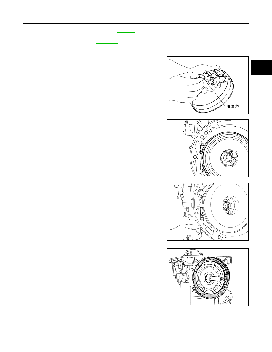
1.
Install brake band and band strut.
a.
Install band strut on brake band.
●
Apply petroleum jelly to band strut.
b.
Place brake band on periphery of reverse clutch drum, and
insert band strut into end of band servo piston stem.
c.
Install anchor end pin on transmission case. Then, tighten
anchor end pin just enough so that reverse clutch drum (clutch
pack) will not tilt forward.
2.
Install input shaft on transmission case.
●
Pay attention to its direction — O-ring groove side is front.
3.
Install gasket on transmission case.
Available oil pump
thrust washer
"Reverse Clutch Drum
End Play"
SAT985A
SAT986A
SAT987A
SAT988A