Nissan Frontier D22. Manual - part 127


  Index      Nissan     Nissan Frontier D22 Pickup (1998-2004 year) - Service and Repair Manual


Search            


Content   ..  125  126  127  128   ..


Nissan Frontier D22. Manual - part 127


PARKING PAWL COMPONENTS

AT-477

[RE4R01A]

D

E

F

G

H

I

J

K

L

M

A

B

AT

Assembly

ECS007QI

1.

Install parking actuator support onto adapter case.

2.

Insert parking pawl shaft into adapter case.
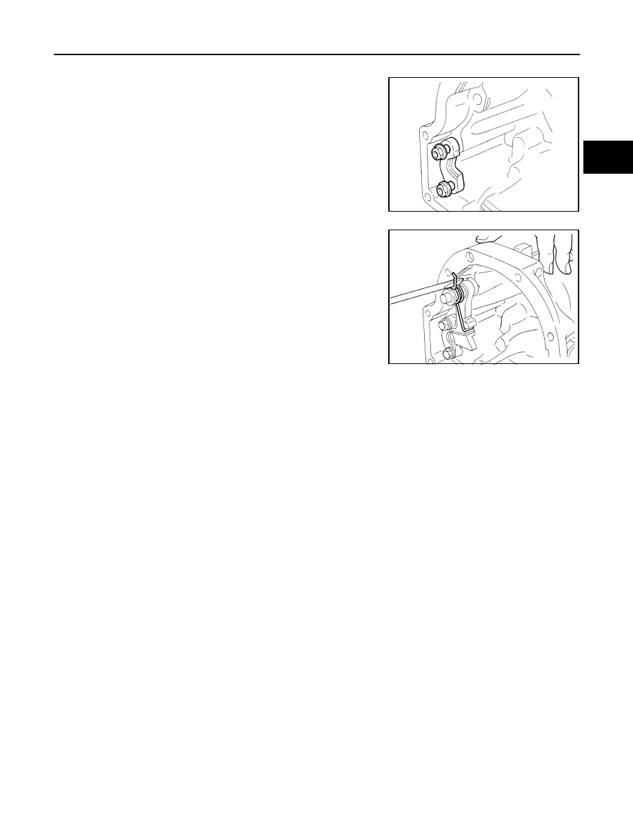
3.

Install return spring, pawl spacer and parking pawl onto parking
pawl shaft.

4.

Bend return spring upward and install it onto adapter case.

SAT229H

SAT226H

AT-478

[RE4R01A]

ASSEMBLY

ASSEMBLY

PFP:00000

Assembly (1)

ECS007QJ

1.

Install manual shaft components.

a.

Install oil seal onto manual shaft.

Apply ATF to oil seal.

Wrap threads of manual shaft with masking tape.

b.

Insert manual shaft and oil seal as a unit into transmission case.

c.

Remove masking tape.

d.

Push oil seal evenly and install it onto transmission case.

e.

Align groove in shaft with drive pin hole, then drive pin into posi-
tion as shown.

f.

Install detent spring and spacer.

g.

While pushing detent spring down, install manual plate onto
manual shaft.

SAT931A

SAT932A

SAT933A

SAT901E

ASSEMBLY

AT-479

[RE4R01A]

D

E

F

G

H

I

J

K

L

M

A

B

AT

h.

Install lock nuts onto manual shaft.

2.

Install accumulator piston.

a.

Install O-rings onto accumulator piston.

Apply ATF to O-rings.

Accumulator piston O-rings

Unit: mm (in)

b.

Install return spring for accumulator A onto transmission case.

c.

Install accumulator pistons A, B, C and D.

Apply ATF to transmission case.

SAT936A

SAT523GA

Accumulator

A

B

C

D

Small diameter end

29 (1.14)

32 (1.26)

45 (1.77)

29 (1.14)

Large diameter end

45 (1.77)

50 (1.97)

50 (1.97)

45 (1.77)

Free length of return 
spring

: Refer to 

AT-497, "Return 

Springs"

 .

SAT938A

SAT939AA

AT-480

[RE4R01A]

ASSEMBLY

3.

Install band servo piston.

a.

Install return springs onto servo piston.

b.

Install band servo piston onto transmission case.

Apply ATF to O-ring of band servo piston and transmis-
sion case.

c.

Install gasket for band servo onto transmission case.

d.

Install band servo retainer onto transmission case.

4.

Install rear side clutch and gear components.

a.

Place transmission case in vertical position.

b.

Slightly lift forward clutch drum assembly. Then slowly rotate it
clockwise until its hub passes fully over clutch inner race inside
transmission case.

SAT941A

SAT942A

SAT940A

SAT943A

SAT944A


Content   ..  125  126  127  128   ..