Nissan Xterra. Manual - part 724


  Index      Nissan     Nissan Xterra (2014 year) - Service and Repair Manual


Search            


Content   ..  722  723  724  725   ..


Nissan Xterra. Manual - part 724


FRONT WIPER AND WASHER SYSTEM

WW-5

< SYSTEM DESCRIPTION >

C

D

E

F

G

H

I

J

K

M

A

B

WW

N

O

P

• BCM transmits the front wiper request signal (INT) to IPDM E/R with CAN communication according to the

front wiper INT operation condition and the intermittent operation delay interval judged value.

Front wiper INT operating condition

- Ignition switch ON

- Front wiper switch INT

Intermittent operation delay interval judgment

- BCM calculates the intermittent operation delay interval from the vehicle speed signal received from the

wiper dial position and the combination meter with CAN communication.

• IPDM E/R turns the integrated front wiper relay ON so that the front wiper is operated only once according to

the front wiper request signal (INT).

• BCM detects stop position/except stop position of the front wiper motor according to the front wiper stop

position signal received from IPDM E/R with CAN communication.

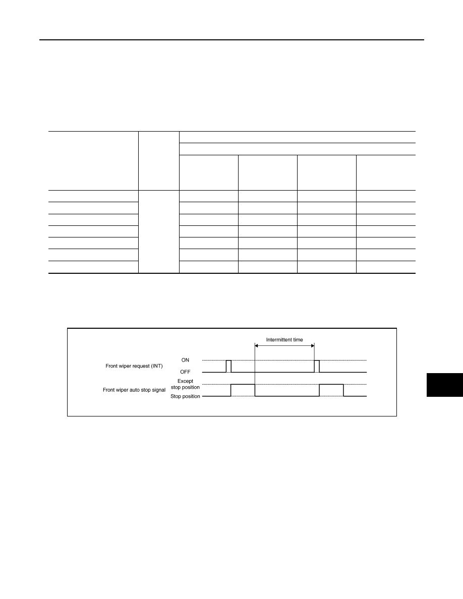
• BCM transmits the front wiper request signal (INT) again after the intermittent operation delay interval after

the front wiper motor is stopped.

FRONT WIPER AUTO STOP OPERATION

• BCM stops transmitting the front wiper request signal when the front wiper switch is turned OFF.

• IPDM E/R detects the front wiper auto stop signal from the front wiper motor and detects the front wiper

motor position (stop position/except stop position).

Wiper intermittent dial posi-

tion

Intermittent 

operation 

interval

Intermittent operation delay Interval (s)

Vehicle speed

Vehicle stopped or 

less than 5 km/h 

(3.1 MPH)

5 km/h (3.1 MPH) 

or more or less 

than 35 km/h (21.7 

MPH)

35 km/h (21.7 

MPH) or more or 

less than 65 km/h 

(40.4 MPH)

65 km/h (40.4 

MPH) or more

1

Short

Long

0.8

0.6

0.4

0.24

2

4

3

2

1.2

3

10

7.5

5

3

4

16

12

8

4.8

5

24

18

12

7.2

6

32

24

16

9.6

7

42

31.5

21

12.6

JPLIA0094GB

WW-6

< SYSTEM DESCRIPTION >

FRONT WIPER AND WASHER SYSTEM

• When the front wiper request signal is stopped, IPDM E/R turns ON the front wiper relay until the front wiper

motor returns to the stop position.

NOTE:

• BCM stops the transmitting of the front wiper request signal when the ignition switch is OFF.

• IPDM E/R turns the front wiper relay OFF when the ignition switch is OFF.

FRONT WIPER OPERATION LINKED WITH WASHER

• BCM transmits the front wiper request signal (LO) to IPDM E/R with CAN communication according to the

washer linked operating condition of the front wiper.

• BCM transmits the front wiper request signal (LO) so that the front wiper operates approximately 3 times

when the front washer switch OFF is detected.

Washer linked operating condition of front wiper

- Ignition switch ON

- Front washer switch ON (0.4 second or more)

• IPDM E/R turns ON the integrated front wiper relay according to the front wiper request signal (LO).

• The front and rear washer motor is grounded through the combination switch with the front washer switch

ON.

FRONT WIPER DROP WIPE OPERATION

• BCM controls the front wiper to operate once according to the conditions of front wiper drop wipe operation.

Front wiper drop wipe operating condition

- Ignition switch ON

- Front wiper switch OFF

- Front washer switch OFF

• BCM transmits the front wiper request signal (LO) to IPDM E/R with CAN communication so that the front

wiper operate once three seconds after front wiper operation linked with washer.

• IPDM E/R turns ON the integrated front wiper relay according to the front wiper request signal (LO).

FRONT WIPER FAIL

−SAFE OPERATION

• IPDM E/R performs the fail-safe function when the front wiper auto stop circuit is malfunctioning. Refer to

PCS-20, "Fail Safe"

.

JPLIA0095GB

FRONT WIPER AND WASHER SYSTEM

WW-7

< SYSTEM DESCRIPTION >

C

D

E

F

G

H

I

J

K

M

A

B

WW

N

O

P

Component Parts Location

INFOID:0000000009484683

Component Description

INFOID:0000000009484684

1.

BCM M18, M20 (view with lower in-
strument panel LH removed)

2.

Front and rear washer motor E105 3.

Washer fluid reservoir

4.

Front wiper motor E23 (view with 
cowl top removed)

5.

IPDM E/R E121, E122, E124

6.

Combination switch (wiper and washer 
switch) M28

ALLIA0617ZZ

Part

Description

BCM

• Judges each switch status by the combination switch reading function.
• Requests (with CAN communication) the front wiper relay and the front wiper high relay ON to 

IPDM E/R.

IPDM E/R

• Controls the integrated relay according to the request (with CAN communication) from BCM.
• Performs the auto stop control of the front wiper.

Combination switch
(Wiper and washer 
switch)

Refer to 

WW-4, "System Diagram"

.

Combination meter

Transmits the vehicle speed signal to BCM with CAN communication.

Front wiper motor

• IPDM E/R controls front wiper operation.
• Sends wiper stop signal to IPDM E/R.

Front and rear washer 
motor

Pumps washer fluid to the front or rear in wash mode.

WW-8

< SYSTEM DESCRIPTION >

REAR WIPER AND WASHER SYSTEM

REAR WIPER AND WASHER SYSTEM

System Diagram

INFOID:0000000009484685

System Description

INFOID:0000000009484686

OUTLINE

The rear wiper is controlled by each function of BCM.

Control by BCM

• Combination switch reading function

• Rear wiper control function

REAR WIPER BASIC OPERATION

• BCM detects the combination switch condition by the combination switch reading function.

• BCM controls the rear wiper to start or stop.

REAR WIPER ON OPERATION

• BCM supplies power to the rear wiper motor according to the rear wiper ON operating condition.

Rear wiper ON operating condition

- Ignition switch ON

- Rear wiper switch ON

REAR WIPER INT OPERATION

• BCM supplies power to the rear wiper motor according to the INT operating condition.

Rear wiper INT operating condition

- Ignition switch ON

- Rear wiper switch INT

• BCM controls the rear wiper to operate once.

• BCM detects the rear wiper motor stopping position.

• BCM supplies power to the rear wiper motor after an intermittent from the stop of the rear wiper motor.

REAR WIPER AUTO STOP OPERATION

• BCM stops supplying power to the rear wiper motor when the rear wiper switch is turned OFF.

AWLIA2158GB

JPLIA0165GB


Content   ..  722  723  724  725   ..