Nissan Xterra. Manual - part 509


  Index      Nissan     Nissan Xterra (2014 year) - Service and Repair Manual


Search            


Content   ..  507  508  509  510   ..


Nissan Xterra. Manual - part 509


MWI

COMPASS

MWI-23

< SYSTEM DESCRIPTION >

C

D

E

F

G

H

I

J

K

L

M

B

A

O

P

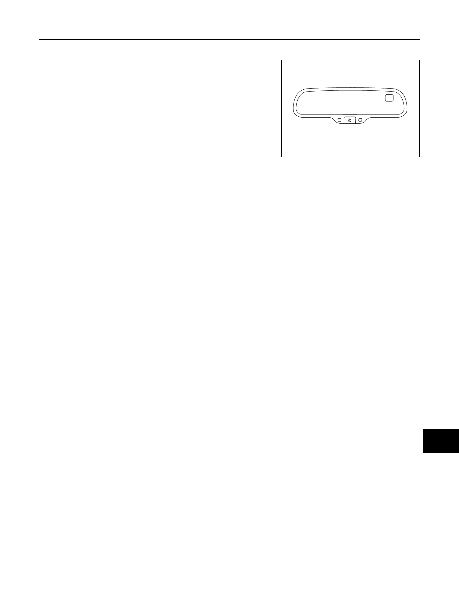
The compass display is equipped with an automatic correction function. If the compass display reads “CAL” or

the direction is not shown correctly, perform the correction procedure below.

1. Press and hold the mode switch until the display reads “CAL”.

2. Drive the vehicle slowly in a circle, in an open, safe place. The

initial calibration is completed in about 3 turns.

NOTE:

In places where the terrestrial magnetism is extremely disturbed, the

initial correction may start automatically.

WKIA4836E

MWI-24

< SYSTEM DESCRIPTION >

DIAGNOSIS SYSTEM (METER)

DIAGNOSIS SYSTEM (METER)

Diagnosis Description

INFOID:0000000009483198

SELF-DIAGNOSIS MODE

The following items can be checked during Combination Meter Self-Diagnosis Mode.

• Gauge sweep and present gauge values.

• Illuminates all odometer/trip meters and A/T indicator segments.

• Illuminates all micro controlled lamps/LEDs regardless of switch position.

• Displays estimated present battery voltage.

• Displays seat belt buckle switch LH status.

OPERATION PROCEDURE

NOTE:

• Once entered, combination meter self-diagnosis mode will function with the ignition switch in ON or START.

Combination meter self-diagnosis mode will exit upon turning the ignition switch to OFF or ACC. 

• If the diagnosis function is activated with trip A displayed, the mileage on trip A is reset to 0000.0. (Trip B

operates the same way.)

To initiate combination meter self-diagnosis mode, refer to the following procedure.

1. Turn the ignition switch ON, while pressing the odometer/trip meter switch for 5 - 8 seconds. When the

diagnosis function is activated, the odometer/trip meter will display tESt.

NOTE:

Check combination meter power supply and ground circuit when self-diagnosis mode of combination meter

does not start. Refer to 

MWI-30, "COMBINATION METER : Diagnosis Procedure"

. Replace combination

meter if normal. Refer to 

MWI-84, "Removal and Installation"

.

COMBINATION METER SELF-DIAGNOSIS MODE FUNCTIONS

To interpret combination meter self-diagnosis mode functions, refer to the following table.

Event

Odometer Display

Description of Test/Data

Notes:

Odometer/trip meter A/B 
switch held from 5 to 8 
seconds (or until re-
leased)

tESt

Initiating self-diagnosis mode

Switch released

GAGE

Performs sweep of all 
gauges, then displays 
present gauge values.

Gauges sweep within 10 seconds

Switch pressed

(All segments illuminated)

Lights all LCD segments. 
Compare with picture.

USA

Canada

Switch pressed

bulb

Illuminates all micro-con-
trolled lamps/LEDs.

Part may not be configured for all 
lamps (functions) that turn on dur-
ing test. This is normal.

Switch pressed

r XXXX, FAIL

Return to normal opera-
tion of all lamps/LEDs and 
displays “r XXXX”.

If a malfunction exists, “FAIL” will 
flash.

AWNIA0219ZZ

AWNIA0220ZZ

MWI

DIAGNOSIS SYSTEM (METER)

MWI-25

< SYSTEM DESCRIPTION >

C

D

E

F

G

H

I

J

K

L

M

B

A

O

P

CONSULT Function (METER/M&A)

INFOID:0000000009483199

CONSULT can display each diagnostic item using the diagnostic test modes shown following.

Switch pressed

nrXXXX

Displays Hex ROM rev as 
stored in NVM.

Switch pressed

EE XX, FAIL

Displays “EE XX”.

If a malfunction exists, “FAIL” will 
flash.

Switch pressed

dtXXXX

Hex coding of final manu-
facturing test date.

Switch pressed
(3 times)

Sc1 XX through Epr XX

Displays 8 bit software 
configuration value in Hex 
format

Switch pressed

1nF XX

Displays 8-bit market info 
value in Hex format.

$31 = USA
$2A = Canada

Switch pressed
(3 times)

cYL XX through tF

N/A

Switch pressed

ot1 XX

Displays oil pressure tell-
tale “” in Hex format.

Switch pressed

ot0 XX

Displays oil pressure tell-
tale “” in Hex format.

Switch pressed

XXXXX

“Corrected” speed value 
in hundredths of MPH. 
Gauge indication may be 
slightly higher. This is nor-
mal.

Will display “-----” if message is not 
received. Will display “99999” if 
data received is invalid.

Switch pressed

XXXXX

“Corrected” speed value 
in hundredths of KPH. 
Gauge indication may be 
slightly different. This is 
normal.

Will display “-----” if message is not 
received. Will display “99999” if 
data received is invalid.

Switch pressed

t XXXX

Tachometer value in 
RPM. Gauge indication 
may be higher at higher 
RPM. This is normal.

Will display “-----” if message is not 
received.

Switch pressed

F1XXXX

Present fuel level A/D in-
put. This input represents 
fuel sender input.

000-009 = Short circuit
010-254 = Normal range
255 = Open circuit

Switch pressed

XXXC

Last temperature gauge 
input value in degrees C. 
Temperature gauge indi-
cates present tempera-
ture per indication 
standard.

Will display “---”C if message is not 
received.
Will display “999” if data received 
is invalid.
High = 130 deg C
Normal = 70 - 105 deg C
Low = less than 50 deg C

Switch pressed

BAtXX.X

Estimated present battery 
voltage.

Switch pressed

rES -X

Seat belt buckle switch LH 
status.

1= Buckled
0 = Unbuckled

Switch pressed
(30 times)

PA -XX through PA1-XX

N/A

Switch pressed

GAGE

Return to beginning of self-diagno-
sis cycle.

Event

Odometer Display

Description of Test/Data

Notes:

MWI-26

< SYSTEM DESCRIPTION >

DIAGNOSIS SYSTEM (METER)

SELF-DIAG RESULTS

Display Item List

Refer to 

MWI-40, "DTC Index"

.

DATA MONITOR

Display Item List

X: Applicable

METER/M&A diagnosis mode

Description

Self Diagnostic Result

Displays combination meter self-diagnosis results.

Data Monitor

Displays combination meter input/output data in real time.

Work Support

Displays diagnosis procedure of each work item.

CAN Diag Support Mntr

The result of transmit/receive diagnosis of CAN communication can be read.

Display item [Unit]

MAIN

SIGNALS

SELECTION 

FROM MENU

Description

SPEED METER [km/h] or [mph]

X

X

Displays the value of vehicle speed signal.

SPEED OUTPUT [km/h] or [mph]

X

X

Displays the value of vehicle speed signal, which is transmitted to 
each unit with CAN communication.

TACHO METER [rpm]

X

X

Displays the value of engine speed signal, which is input from ECM.

W TEMP METER [

°C] or [°F]

X

X

Displays the value of engine coolant temperature signal, which is in-
put from ECM. 

FUEL METER [lit.]

X

X

Displays the value, which processes a resistance signal from fuel 
gauge.

DISTANCE [km] or [mile]

X

X

Displays the value, which is calculated by vehicle speed signal, fuel 
gauge and fuel consumption from ECM.

FUEL W/L [ON/OFF]

X

X

Displays [ON/OFF] condition of low-fuel warning lamp.

C-ENG W/L [ON/OFF] 

X

Displays [ON/OFF] condition of malfunction indicator lamp.

AIR PRES W/L [ON/OFF]

X

Displays [ON/OFF] condition of tire pressure warning lamp.

SEAT BELT W/L [ON/OFF]

X

Indicates [ON/OFF] condition of seat belt warning lamp.

BUZZER [ON/OFF]

X

X

Displays [ON/OFF] condition of buzzer.

DOOR W/L [ON/OFF]

X

Displays [ON/OFF] condition of door ajar warning lamp.

HI-BEAM IND [ON/OFF]

X

Displays [ON/OFF] condition of high beam indicator.

TURN IND [ON/OFF]

X

Displays [ON/OFF] condition of turn indicator.

OIL W/L [ON/OFF]

X

Displays [ON/OFF] condition of oil pressure warning lamp.

VDC/TCS IND [ON/OFF]

X

Displays [ON/OFF] condition of VDC OFF indicator lamp.

ABS W/L [ON/OFF]

X

Displays [ON/OFF] condition of ABS warning lamp.

SLIP IND [ON/OFF]

X

Displays [ON/OFF] condition of SLIP indicator lamp.

BRAKE W/L [ON/OFF]

X

Displays [ON/OFF] condition of brake warning lamp.*

O/D OFF SWITCH [ON/OFF]

X

Indicates [ON/OFF] condition of O/D OFF switch.

P RANGE IND [ON/OFF] 

X

X

Indicates [ON/OFF] condition of A/T shift P range indicator.

R RANGE IND [ON/OFF]

X

X

Indicates [ON/OFF] condition of A/T shift R range indicator.

N RANGE IND [ON/OFF]

X

X

Indicates [ON/OFF] condition of A/T shift N range indicator.

D RANGE IND [ON/OFF]

X

X

Indicates [ON/OFF] condition of A/T shift D range indicator.

3 RANGE IND [ON/OFF]

X

X

Indicates [ON/OFF] condition of A/T shift 3 range indicator.

2 RANGE IND [ON/OFF]

X

X

Indicates [ON/OFF] condition of A/T shift 2 range indicator.

1 RANGE IND [ON/OFF]

X

X

Indicates [ON/OFF] condition of A/T shift 1range indicator.

O/D OFF W/L [ON/OFF]

X

Displays [ON/OFF] condition of O/D OFF warning lamp.

CRUISE IND [ON/OFF]

X

Displays [ON/OFF] condition of CRUISE indicator.


Content   ..  507  508  509  510   ..