Nissan Xterra. Manual - part 508


  Index      Nissan     Nissan Xterra (2014 year) - Service and Repair Manual


Search            


Content   ..  506  507  508  509   ..


Nissan Xterra. Manual - part 508


MWI

METER SYSTEM

MWI-19

< SYSTEM DESCRIPTION >

C

D

E

F

G

H

I

J

K

L

M

B

A

O

P

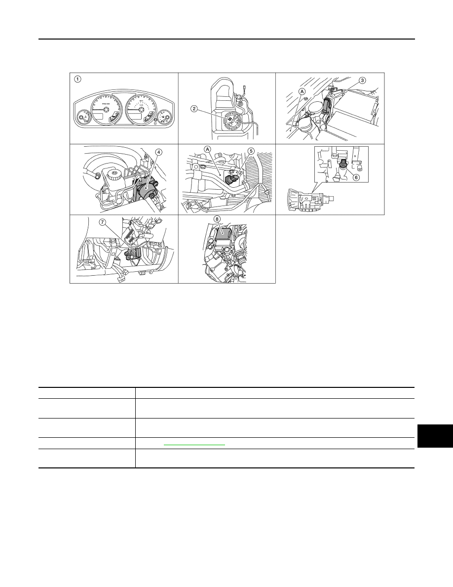
WARNING LAMPS/INDICATOR LAMPS : Component Parts Location

INFOID:0000000009483191

WARNING LAMPS/INDICATOR LAMPS : Component Description

INFOID:0000000009483192

TRIP COMPUTER

AWNIA0775ZZ

1.

Combination meter M24

2.

Fuel level sensor unit and fuel pump C5 
(view with fuel tank removed)

3.

ECM E16 (view with ECM cover re-
moved)
A. Coolant reservoir

4.

ABS actuator and electric unit (control 
unit) E125

5.

Oil pressure switch E208
A. Oil pan (upper)

6.

A/T assembly F9

7.

BCM M18, M19 (view with lower instru-
ment panel LH removed)

8.

IPDM E/R E122, E124

Unit

Description

Combination meter

Turns the oil pressure warning lamp ON/OFF according to the oil pressure switch signal received 
from BCM by means of communication. 

IPDM E/R

Reads the ON/OFF signals from the oil pressure switch and transmits the oil pressure switch signal 
to the combination meter via BCM with the CAN communication line. 

Oil pressure switch

Refer to 

MWI-36, "Description"

BCM

Transmits the oil pressure switch signal received from IPDM E/R via CAN communication to the 
combination meter via CAN communication. 

MWI-20

< SYSTEM DESCRIPTION >

METER SYSTEM

TRIP COMPUTER : System Diagram

INFOID:0000000009483193

TRIP COMPUTER : System Description

INFOID:0000000009483194

FUNCTION

The trip computer can indicate the following items.

• DTE (distance to empty)

• Trip distance

• Trip time

• Average fuel consumption

• Average vehicle speed

DTE (DISTANCE TO EMPTY) INDICATION

The range indication provides the driver with an estimation of the distance that can be driven before refueling.

The range is calculated by signals from the fuel level sensor unit (fuel remaining), ECM (fuel consumption)

and the ABS actuator and electric unit (vehicle speed). The indication will be refreshed every 30 seconds.
When fuel remaining is less than approximately 11.6  (3 1/8 US gal, 2 1/2 Imp gal), the indication will blink as
a warning. If the fuel remaining is less than approximately 9.6  (2 1/2 US gal, 2 1/8 Imp gal), the indication will

show “---”. In this case, the display will change to the DTE mode even though the display is showing a different

mode. When the battery is disconnected and reconnected, DTE mode will display “---” until the vehicle is

driven 0.3 miles (0.5 km).

TRIP DISTANCE

Trip distance is calculated by signal from the ABS actuator and electric unit (vehicle speed). If trip distance is

reset, trip time will be reset at the same time.

TRIP TIME

Trip time displays cumulative ignition switch ON time. If trip time is reset, trip distance will be reset at the same

time.

AVERAGE FUEL CONSUMPTION

Average fuel consumption indication is calculated by signals from the ABS actuator and electric unit (vehicle

speed) and the ECM (fuel consumption). The indication will be refreshed every 30 seconds.

AVERAGE VEHICLE SPEED

Average vehicle speed indication is calculated by running distance and running time. The indication will be

refreshed every 30 seconds. If average vehicle speed is reset, average fuel consumption will be reset at the

same time. After resetting, the display will show “---” for 30 seconds.

HOW TO CHANGE/RESET INDICATION

Refer to Owner's Manual for trip computer operating instructions.

AWNIA0218GB

MWI

METER SYSTEM

MWI-21

< SYSTEM DESCRIPTION >

C

D

E

F

G

H

I

J

K

L

M

B

A

O

P

TRIP COMPUTER : Component Parts Location

INFOID:0000000009483195

TRIP COMPUTER : Component Description

INFOID:0000000009483196

AWNIA0775ZZ

1.

Combination meter M24

2.

Fuel level sensor unit and fuel pump C5 
(view with fuel tank removed)

3.

ECM E16 (view with ECM cover re-
moved)
A. Coolant reservoir

4.

ABS actuator and electric unit (control 
unit) E125

5.

Oil pressure switch E208
A. Oil pan (upper)

6.

A/T assembly F9

7.

BCM M18, M19 (view with lower instru-
ment panel LH removed)

8.

IPDM E/R E122, E124

Unit

Description

Combination meter

Controls the information display according to the signal received from each unit. 

Fuel level sensor unit

Refer to 

MWI-33, "Description"

.

ECM

Transmits the following signals to the combination meter via CAN communication line.

• Engine speed signal

• Fuel consumption monitor signal

ABS actuator and electric unit 
(control unit)

Transmits the vehicle speed signal to the combination meter via CAN communication line.

MWI-22

< SYSTEM DESCRIPTION >

COMPASS

COMPASS

Description

INFOID:0000000009483197

DESCRIPTION

With the ignition switch in the ON position, and the mode switch ON,

the compass display will indicate the direction the vehicle is heading.

Vehicle direction is displayed as follows:

• N: north

• E: east

• S: south

• W:  west

ZONE VARIATION SETTING PROCEDURE

The difference between magnetic north and geographical north can sometimes be great enough to cause

false compass readings. This difference is known as variance. In order for the compass to operate properly

(accurately) in a particular zone, the zone variation must be calibrated using the following procedure. 

Zone Variation Chart

1. Determine your location on the zone map.
2. Turn the ignition switch to the ON position.
3. Press and hold the mode switch until the current zone number appears in the display.
4. Press the mode switch repeatedly until the desired zone number appears in the display.
Once the desired zone number is displayed, stop pressing the mode switch and the display will show a com-

pass direction after a few seconds.

NOTE:

Use zone number 5 for Hawaii.

CALIBRATION PROCEDURE

WKIA4836E

WKIA4148E


Content   ..  506  507  508  509   ..