Nissan Xterra. Manual - part 349
EM-24
< REMOVAL AND INSTALLATION >
[VQ40DE]
AIR CLEANER AND AIR DUCT
REMOVAL AND INSTALLATION
AIR CLEANER AND AIR DUCT
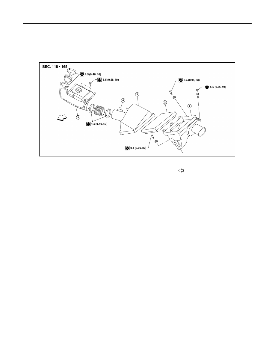
Exploded View
INFOID:0000000009484450
Removal and Installation
INFOID:0000000009484451
NOTE:
Add marks as necessary for easier installation.
REMOVAL
1. Remove engine room cover (if equipped).
2. Disconnect the harness connector from mass air flow sensor.
3. Disconnect crankcase ventilation hose.
4. Remove the air duct and resonator assembly and air cleaner case (upper).
5. Remove air cleaner filter and air cleaner case (lower).
6. If necessary remove the mass air flow sensor from the air cleaner case (upper)
CAUTION:
Handle mass air flow sensor with care.
• Do not shock it.
• Do not disassemble it.
• Do not touch its sensor.
INSPECTION AFTER REMOVAL
Inspect air duct and resonator assembly for cracks or tears.
• Replace air duct and resonator assembly as necessary.
INSTALLATION
Installation is in the reverse order of removal.
1.
Air cleaner case (lower)
2.
Air cleaner filter
3.
Air cleaner case (upper)
4.
Mass air flow
5.
Air duct and resonator
Front
AWBIA1521ZZ