Nissan Xterra. Manual - part 347
EM-16
< PERIODIC MAINTENANCE >
[VQ40DE]
SPARK PLUG
SPARK PLUG
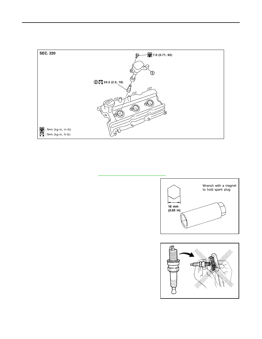
Exploded View
INFOID:0000000009484446
Removal and Installation
INFOID:0000000009484447
REMOVAL
1. Remove the ignition coil. Refer to
EM-40, "Removal and Installation"
.
2. Remove the spark plug using a suitable tool.
CAUTION:
Do not drop or shock it.
INSPECTION AFTER REMOVAL
• Do not use a wire brush for cleaning.
• If the spark plug tip is covered with carbon, spark plug cleaner may be used.
1.
Ignition coil
2.
Spark plug
PBIC2901E
SEM294A
SMA773C