Nissan Xterra. Manual - part 296


  Index      Nissan     Nissan Xterra (2014 year) - Service and Repair Manual


Search            


Content   ..  294  295  296  297   ..


Nissan Xterra. Manual - part 296


EC-310

< DTC/CIRCUIT DIAGNOSIS >

[VQ40DE]

P0447 EVAP CANISTER VENT CONTROL VALVE

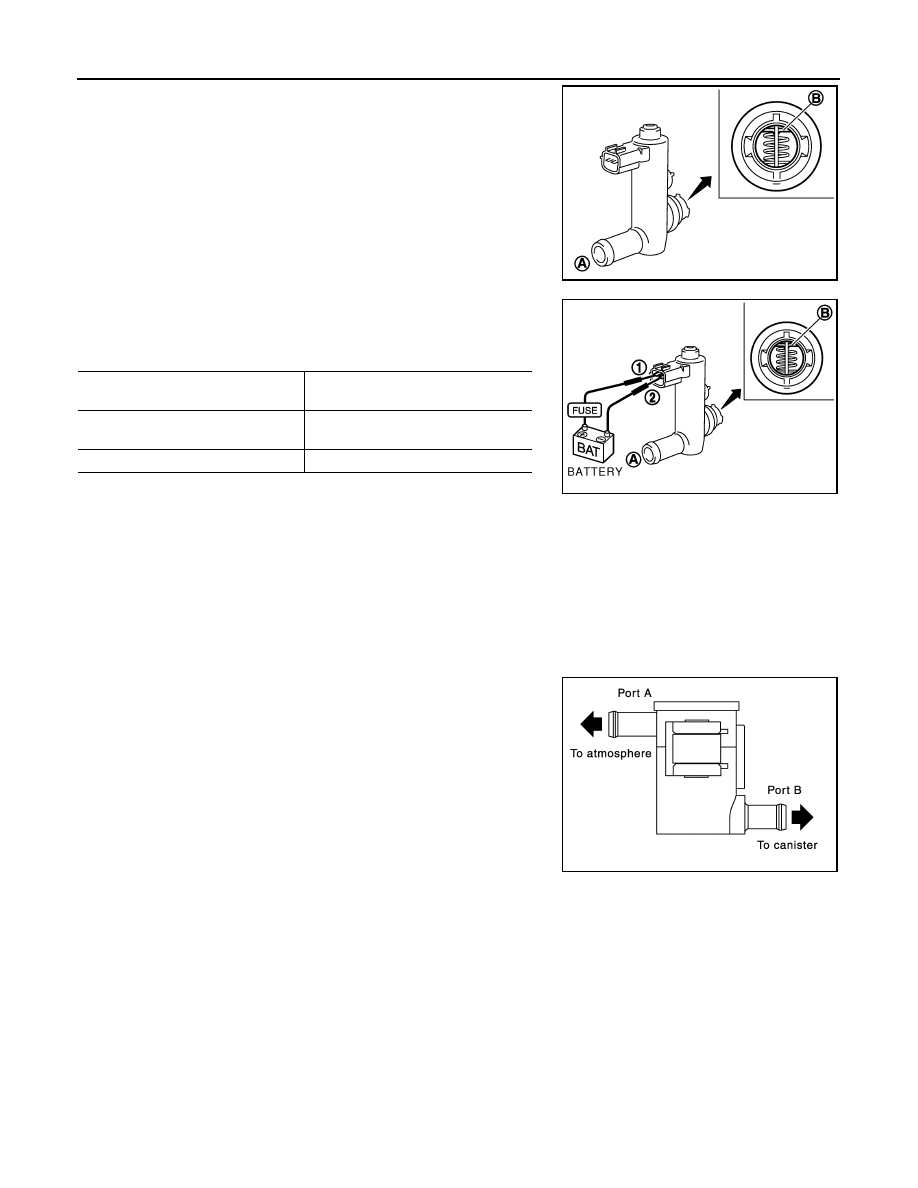
2. Check portion B of EVAP canister vent control valve for being

rusted.

3. Check air passage continuity and operation delay time under the

following conditions.

Make sure that new O-ring is installed properly.

Operation takes less than 1 second.

If NG, go to next step.

4. Clean the air passage (portion A to B) of EVAP canister vent control valve using an air blower.
5. Perform step 3 again.
6. If NG, replace EVAP canister vent control valve.

DRAIN FILTER

1. Check visually for insect nests in the drain filter air inlet.
2. Check visually for cracks or flaws in the appearance.
3. Check visually for cracks or flaws in the hose.
4. Blow air into port A and check that it flows freely out of port B.
5. Block port B.
6. Blow air into port A and check that there is no leakage.
7. If NG, replace drain filter.

PBIB1033E

Condition

Air passage continuity

 between (A) and (B)

12V direct current supply between
 terminals 1 and 2

No

OFF

Yes

PBIB1034E

PBIB3641E

P0448 EVAP CANISTER VENT CONTROL VALVE

EC-311

< DTC/CIRCUIT DIAGNOSIS >

[VQ40DE]

C

D

E

F

G

H

I

J

K

L

M

A

EC

N

P

O

P0448 EVAP CANISTER VENT CONTROL VALVE

Component Description

INFOID:0000000009484015

The EVAP canister vent control valve (3) is located on the EVAP

canister (4) and is used to seal the canister vent.

This solenoid valve responds to signals from the ECM. When the

ECM sends an ON signal, the coil in the solenoid valve is energized.

A plunger will then move to seal the canister vent. The ability to seal

the vent is necessary for the on board diagnosis of other evaporative

emission control system components.

This solenoid valve is used only for diagnosis, and usually remains

opened.

When the vent is closed, under normal purge conditions, the evapo-

rative emission control system is depressurized and allows EVAP

Control System diagnosis.

• Fuel filler pipe (1)

• EVAP control system pressure sensor (2)

• Drain filter (5)

: Vehicle front

On Board Diagnosis Logic

INFOID:0000000009484016

DTC Confirmation Procedure

INFOID:0000000009484017

NOTE:

If DTC Confirmation Procedure has been previously conducted, always perform the following before conduct-

ing the next step.

1. Turn ignition switch OFF and wait at least 10 seconds.

2. Turn ignition switch ON.

3. Turn ignition switch OFF and wait at least 10 seconds.

 WITH CONSULT

1. Turn ignition switch ON and wait at least 5 seconds.
2. Turn ignition switch OFF and wait at least 10 seconds.
3. Turn ignition switch ON and select “DATA MONITOR” mode with CONSULT.
4. Start engine and let it idle for at least 1 minute. 
5. Repeat next procedures 3 times.

PBIB3642E

AWBIA0223ZZ

DTC No.

Trouble diagnosis name

DTC detecting condition

Possible cause

P0448
0448

EVAP canister vent con-
trol valve close

EVAP canister vent control valve remains 
closed under specified driving conditions.

• EVAP canister vent control valve
• EVAP control system pressure sensor 

and the circuit

• Blocked rubber tube to EVAP canister 

vent control valve

• Drain filter
• EVAP canister is saturated with water

EC-312

< DTC/CIRCUIT DIAGNOSIS >

[VQ40DE]

P0448 EVAP CANISTER VENT CONTROL VALVE

a. Increase the engine speed up to between 3,000 and 3,500 rpm and maintain that speed for 2 minutes and

50 seconds to 3 minutes.

Do not exceed 3 minutes.

b. Fully released accelerator pedal and keep engine idle for about 5 seconds.
6. Check 1st trip DTC.
7. If 1st trip DTC is detected, go to 

EC-312, "Diagnosis Procedure"

.

If 1st trip DTC is not detected, go to the next step.

8. Repeat next procedure 20 times.
a. Quickly increase the engine speed up to between 4,000 and 4,500 rpm or more and maintain that speed

for 25 to 30 seconds.

b. Fully released accelerator pedal and keep engine idle for at least 35 seconds.

9. Check 1st trip DTC.
10. If 1st trip DTC is detected, go to 

EC-312, "Diagnosis Procedure"

.

 WITH GST

Follow the procedure “WITH CONSULT” above.

Diagnosis Procedure

INFOID:0000000009484018

1.

CHECK RUBBER TUBE

1. Turn ignition switch OFF.

2. Disconnect rubber tube connected to EVAP canister vent control

valve (3).

-

Fuel filler pipe (1)

-

EVAP control system pressure sensor (2)

-

EVAP canister (4)

-

Drain filter (5)

-

: Vehicle front

3. Check the rubber tube for clogging.
OK or NG

OK

>> GO TO 2.

NG

>> Clean rubber tube using an air blower.

2.

CHECK DRAIN FILTER

Refer to 

EC-309, "Component Inspection"

.

OK or NG

OK

>> GO TO 3.

NG

>> Replace drain filter.

3.

CHECK EVAP CANISTER VENT CONTROL VALVE

Refer to 

EC-313, "Component Inspection"

.

OK or NG

OK

>> GO TO 4.

NG

>> Replace EVAP canister vent control valve. Refer to 

FL-16, "Removal and Installation"

.

4.

CHECK IF EVAP CANISTER SATURATED IS WITH WATER

JMBIA1516GB

AWBIA0223ZZ

P0448 EVAP CANISTER VENT CONTROL VALVE

EC-313

< DTC/CIRCUIT DIAGNOSIS >

[VQ40DE]

C

D

E

F

G

H

I

J

K

L

M

A

EC

N

P

O

1. Remove EVAP canister with EVAP canister vent control valve and EVAP control system pressure sensor

attached.

2. Check if water will drain from the EVAP canister.
Yes or No

Yes

>> GO TO 5.

No

>> GO TO 7.

5.

CHECK EVAP CANISTER

Weigh the EVAP canister with the EVAP canister vent control valve and EVAP control system pressure sensor

attached.

The weight should be less than 2.0 kg (4.4 lb).
OK or NG

OK

>> GO TO 7.

NG

>> GO TO 6.

6.

DETECT MALFUNCTIONING PART

Check the following.

• EVAP canister for damage

• EVAP hose between EVAP canister and drain filter for clogging or poor connection

>> Repair hose or replace EVAP canister. Refer to 

FL-16, "Removal and Installation"

.

7.

CHECK EVAP CONTROL SYSTEM PRESSURE SENSOR CONNECTOR

1. Disconnect EVAP control system pressure sensor harness connector.

2. Check connectors for water.

OK or NG

OK

>> GO TO 8.

NG

>> Replace EVAP control system pressure sensor. Refer to 

FL-16, "Removal and Installation"

.

8.

CHECK EVAP CONTROL SYSTEM PRESSURE SENSOR

Refer to 

EC-323, "Component Inspection"

.

OK or NG

OK

>> GO TO 9.

NG

>> Replace EVAP control system pressure sensor. Refer to 

FL-16, "Removal and Installation"

.

9.

CHECK INTERMITTENT INCIDENT

Refer to 

GI-40, "Intermittent Incident"

.

>> INSPECTION END

Component Inspection

INFOID:0000000009484019

EVAP CANISTER VENT CONTROL VALVE

 With CONSULT

1. Remove EVAP canister vent control valve from EVAP canister.

BBIA0558E

Water should not exist.


Content   ..  294  295  296  297   ..