Nissan March K13. Manual - part 542
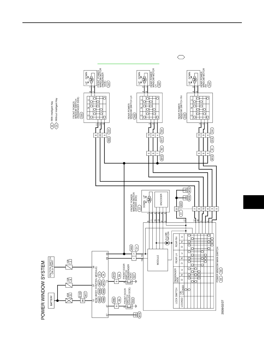
POWER WINDOW SYSTEM
PWC-11
< WIRING DIAGRAM >
C
D
E
F
G
H
I
J
L
M
A
B
PWC
N
O
P
WIRING DIAGRAM
POWER WINDOW SYSTEM
Wiring Diagram
INFOID:0000000005978548
For connector terminal arrangements, harness layouts, and alphabets in a
(option abbreviation; if not
described in wiring diagram), refer to
GI-12, "Connector Information"
JCKWM2861GB